Using the Control Board

Once you have built the board, you can start using it to control your soft fluidic actuators. This section contains some guidelines on using the board. For basic testing of your actuators (e.g. the type of motion they undergo when inflated, checking for leaks) it is probably sufficient to operate the board manually by using the switches and the potentiometer to vary the pressure and open and close the valves. You can also use the Arduino IDE to write some code that will automate the operation of the control board, for example if you want to test the fatigue strength of your actuator or you want to test out some predefined motion sequences. The Basic Control page discusses how to use the board in these ways.
For more advanced control, you can also use the Arduino IDE to write control software. Alternatively, you can use environments such as LabVIEW or Simulink to create the control or data acquisition software to run on the microcontroller. The Advanced Control page discusses some of these options.
Basic Control
Note: Always check the maximum air supply you provide to the system. Every component has its own specifications and can withstand different maximum pressures.
Basic Arduino control
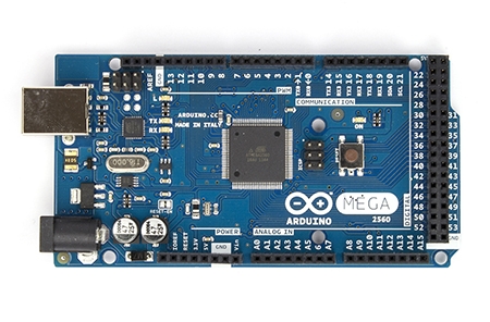
Once the board has been wired following the assembly instructions, we need to program the Arduino Mega microcontroller. If you haven't done so already, set up your Arduino board using the official setup guide: Windows / Mac
If you were able to get the guide's Blink example to work, upload the sample code to control the board hardware. Those already familiar with Arduino programming can customize the code to fit their own needs.
Basic manual control
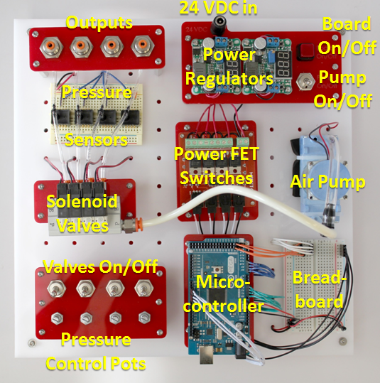
- Power the board by plugging in the 24 VDC power adapter.
- Press the "Board On/Off" button. The two power regulators should turn on and display outputs of 5 and 12 volts.
- Slowly turn one of the 4 potentiometer dials that control the valves. The solenoid valves should start actuating (they will make clicking noises) and a corresponding red light on top of the valve should blink. If nothing happens, try flipping the corresponding valve on/off switch. As you turn the dial, the actuation duty cycle (the ratio of the valve's on time to its off time) should vary.
- While a valve is actuating, slowly adjust the potentiometer on the breadboard (the one connected to Arduino pin A7). The frequency at which the valve actuates should change.
- Flip the "Pump On/Off" switch. The pump should turn on.
- While the pump is on, adjust the various potentiometer dials and feel the air coming out of the board outputs. The airflow should vary as you turn the dials.
- Plug in the USB cable to the Arduino board if it isn't already. Open the serial monitor. The pressure readings for each output (in PSI) should be displayed and continuously updating.
| Control Board PWM Code.txt | 2 KB |
Advanced Control
Advanced Control with the Arduino IDE
One of the advantages of using the Arduino microcontroller is the massive amount of support documentation and useful code libraries that are available. If there is a particular control architecture you wish to implement, there is a good chance that someone has published related Arduino code online. For example, see this guide to PID control using the Arduino, and this PID Arduino library.
Advanced Control with LabVIEW
LabVIEW is a development environment from National Instruments that uses a graphical programming language. Software code is created by dragging and dropping functional blocks and creating connections between these blocks. The following "virtual instrument", used in testing the performance of a PneuNets Bending Actuator, was created in LabVIEW.

The LabVIEW Interface For Arduino Toolkit can be used to create Arduino sketches in the LabVIEW environment.
Advanced Control with Simulink
Simulink from Mathworks is also a graphical programming language in which code is created by manipulating functional blocks in the development environment. One of the advantages of environments like LabVIEW and Simulink is that a designer can make use of provided robust algorithms, without having to make their controllers from scratch. The following block diagram was made in Simulink and used to implement closed-loop control of a PneuNets Bending Actuator.

The Arduino Support package for MATLAB allows you to develop software/algorithms using Simulink’s graphical programming language and download this algorithm to an Arduino device. The package has a built-in compiler that converts the block diagram into code that can be embedded and run remotely on the Arduino. This page contains details on how to set up and use the support package.
Using Simulink with Arduino
This page describes the steps required to set up Simulink to work with Arduino. The instructions assume that you have MATLAB installed on your computer.
To use Simulink to create code that can be run on the Arduino, we need to install the Arduino Support Package from Simulink. We can install the support package from directly within the MATLAB environment. To do this, do the following:
- Open up MATLAB.
- Navigate to Resources/Add-Ons and click the drop-down arrow.
- Click “Get Hardware Support Packages”
- When the Support Package Installer box opens up, select “Install from Internet”.
- A box that looks like the following will open up. Select ‘Arduino’ in the box on the left, and check ‘Install’ for the entry that has ‘Simulink’ under the Required Base Product (this should be the only entry).
- Follow through with the installation

Using the Arduino Support Package
- In the MATLAB command prompt, type in simulink and hit ‘enter’.
- When the library browser opens up, scroll down and you should see a new library entitled ‘Simulink Support Package for Arduino.’
- You can drag-and-drop these blocks into your model as you would normal Simulink blocks. You can also use blocks from other libraries.
