Dielectric Elastomer Actuators
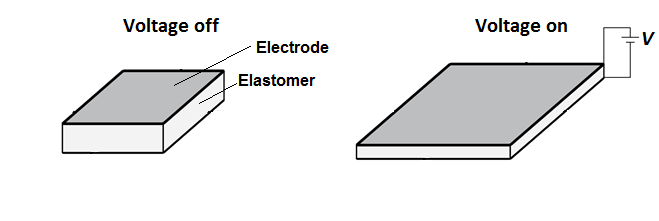
Dielectric elastomers actuators (DEA) are a class of electroactive polymers which work based on inducing of deformation with an electric field, which was demonstrated in 1880 by Wilhelm Conrad Roentgen by spraying charges on a piece of natural rubber (Röntgen 1880). A common design of DEAs is to sandwich a soft insulating elastomer membrane between two compliant electrodes. When a voltage is applied between the electrodes, the arising electric field causes a decrease in thickness and increase in area of the membrane (Pelrine 2000, Suo 2010).
Actuation strains of up to 1692% (Keplinger 2012) have been achieved and a theoretical maximum energy density of 1.4 J/g (Koh 2009) was calculated. DEAs, also called artificial muscles, can be used to create diverse devices such as a linear actuator and a fish-like blimp.
DEAs behave like deformable capacitors and can therefore also be used for energy generation (Pelrine 2001). The following video shows a dielectric elastomer that is used to power LEDs:
This documentation set contains files and instructions to support the design, fabrication, modeling, and testing of a specific Dielectric Elastomer Actuator. We also provide other examples of ways DEAs have been used, including a transparent loudspeaker in our Case Studies page. While we focus on a particular example of a DEA, the principles and guidelines presented here can be adapted to produce a wide range of dielectric elastomer actuators and devices using them.
| Some of the information contained in this web site includes intellectual property covered by both issued and pending patent applications. It is intended solely for research, educational and scholarly purposes by not-for-profit research organizations. If you have interest in specific technologies for commercial applications, please contact us here. |
Design
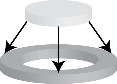
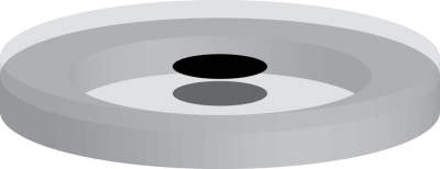
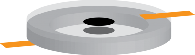
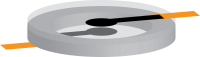
The dielectric elastomer actuators documented in this section consist of a soft, prestretched, dielectric membrane that is attached to a rigid circular frame. This section describes the overall design of the actuators as well as some of the design considerations involved in making your own actuator.
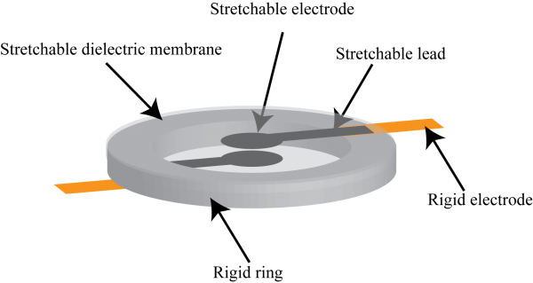
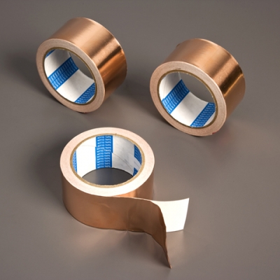
Circular stretchable electrodes made of carbon grease are painted in the center of the membrane on both faces. Each electrode is connected to the edge of the membrane through stretchable leads also made of carbon grease, but painted in opposite directions to avoid overlap of the two leads. At the rigid frame, the stretchable leads are interfaced with the environment through metallic electrodes made using copper tape. Upon application of a voltage the circular electrodes expand and the membrane decreases in thickness.
This design presented here is far from the only design possible for dielectric elastomer actuators. In fact, the working principle of dielectric elastomer actuators allows for a large number of different designs. The type of actuator described here is often used as a reference design to study the influence of material parameters such as electric constant, stiffness, and viscoelasticity on actuation performance. In addition, the influence of varying the prestretch, actuation voltage and actuation frequency can easily be investigated with this type of actuator. See the sections on material and morphology variations for discussions of how varying some of these design parameters affect the performance of the final design.
Variation: Material
Theoretically every soft, stretchable, insulating elastomer membrane can be used in dielectric elastomer actuators. However, the actuation performance is strongly influenced by the properties of the material. Materials with low stiffness and large fracture stretch often show larger actuation strains than stiff materials. The electric constant of the material determines the size of the Maxwell stress (see Modeling section) and therefore the amount of deformation the actuator undergoes. Materials with large dielectric breakdown strength allow the application of larger voltages and therefore larger actuation strains. On the other hand, viscoelasticity reduces the response time and efficiency of the actuators and these parameters are interconnected in many materials, so a compromise between these parameters has to be found.
The most studied classes of materials for dielectric elastomer actuators are acrylates, silicones and polyurethanes. The properties of exemplary materials are shown in the table below. Acrylic elastomers often have a high dielectric constants and dielectric breakdown strengths, but can have a pronounced viscoelastic behavior that limits the speed of actuation. Silicones usually have lower dielectric constants, but are also less viscous. Polyurethanes are a large class of materials and can have, depending on the formulation, very different properties. By changing the building blocks of the material, the properties of polyurethanes can be tailored to specific applications.

Variation: Prestretch
The prestretch of the membrane is a very important parameter to influence the performance of dielectric elastomer actuators. When the dielectric membrane is prestretched, it decreases in thickness. Since the size of the Maxwell stress is determined by the electric field across the membrane (see Modeling section), smaller voltages are required to obtain the same Maxwell stress when the membrane is prestretched.
The more important influence of the prestretch on the actuation performance is that it moves the occurrence of electromechanical instability (see Modeling section) to larger strains or even completely removes it, so that larger strains are possible before failure.
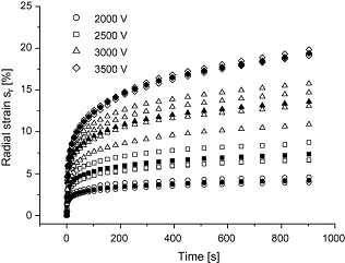
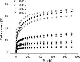
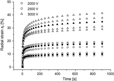
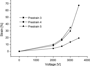
The following figures show the results of a study that investigates the effect of prestretch on the performance of circular dielectric elastomer actuators:
|
Prestretch 3x3 |
Prestretch 4x4 |
|
Prestretch 5x5 |
(Strain after 900s as function of voltage for different prestrains) |
Fabrication
As mentioned previously, there are many variations of designs and materials for dielectric elastomer actuators, which can require different techniques to create. The following section provides step by step instructions on the manufacture of a circular dielectric elastomer actuator on a rigid frame, made with VHB 4910 as the dielectric and electrodes made of carbon grease.
The dielectric elastomer used in this documentation is VHB 4910 because it is a sticky tape which can adhere to the acrylic frame on its own. If other materials are used for the membrane, clamps or glue may be used to attach it to the frame.
Process Overview
The manufacturing process can be divided into the following steps:
1. Prestretching of the membrane onto the rigid frame.
2. Painting of the active area with carbon grease.
3. Application of copper leads.
4. Connecting active area with copper tapes.
Get Started
First visit the Bill of Materials page to make sure you have the necessary materials and then continue on to Step 1 to begin building your own actuator!
Bill of Materials
Materials
|
|
|
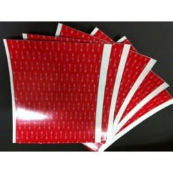
VHB 4910** |
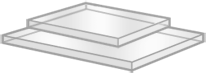
Acrylic to make frame |
|
|
|
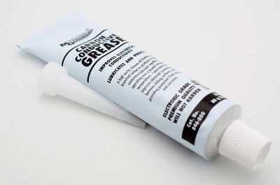
Carbon grease |
Copper tape |
** use red backing to make stencils for prestretching and active area. This material doesn't stick to the VHB so it is very easy to work with.
Tools
|
|
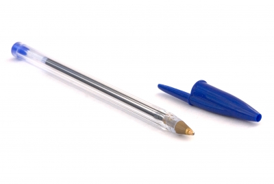
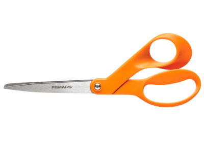
| Pen | Scissors |
|
|
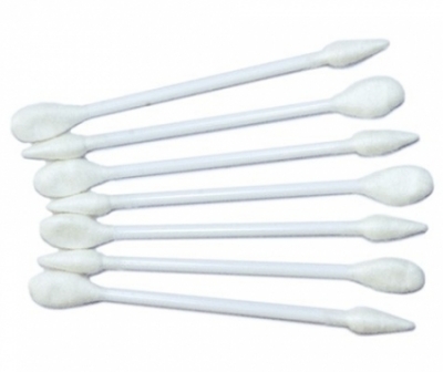
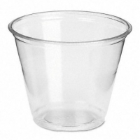
| Cotton Swabs (Q-Tips work fine) | Plastic Cup |

|
|
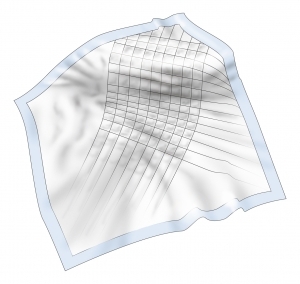
| Gloves | Disposable underlay |
|
|
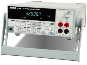
|
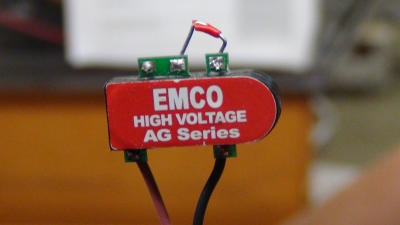
High Voltage Amplifier |
Voltage source (signal generator if possible) |
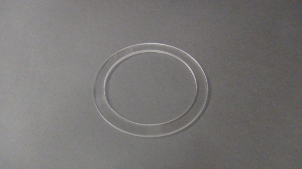
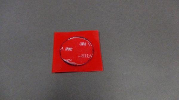
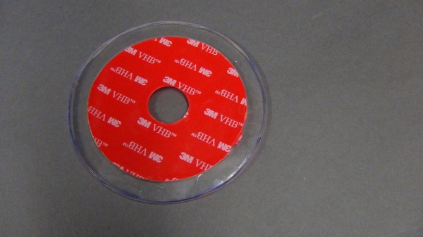
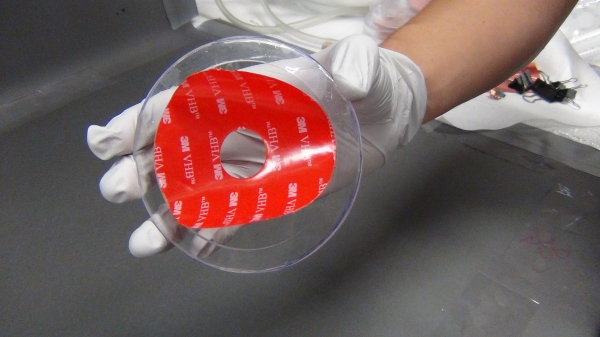
Pre-step: Make stencils and frame
The circular actuator fabricated in this documentation uses an equibiaxial prestretch of 3 (i.e. the membrane is stretched three times equally in all directions). In order to achieve this prestretch, the acrylic frame and the initial piece of VHB must have the correct dimension ratio (3:1). The important dimensions to consider are the outside diameter of the acrylic frame and the outer diameter of the stencil used to cutout the initial piece of VHB.
We make the rigid frame out of acrylic so that it can be reused multiple times. The VHB can be simply peeled off and the frame washed in order to use it again. The two stencils are made using the red cover foil that is attached to VHB 4910 when it is sold from 3M, because it does not stick to VHB and therefore does not damage it upon removal.
 |
|
 |
|
 |
|
Step 1: Prestretching
Make sure to start with a clean working area. It is not necessary to have a perfectly clean actuator, but dust and debris can damage the membrane, leading to a failed actuator.
Do not use gloves for this step. The VHB sticks to the glove material and makes working with it difficult.
 |
|
 |
|
 |
 |
|
 |
|
|
Step 2: Paint Active Area
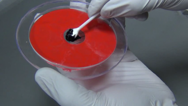
Working with Carbon Grease
Carbon grease is a material that quickly contaminates the whole workspace including clothes and shoes. Always wear gloves as soon as carbon grease is applied to the membrane and use a disposable underlay. If you value the clothing you are wearing, immediately change a glove if it becomes dirty in order to avoid any further contamination.
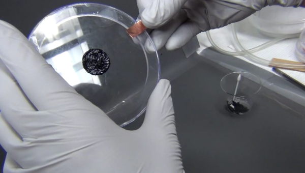
Before painting, put some of the carbon grease from the tube into a plastic cup for easier handling.
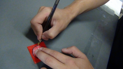
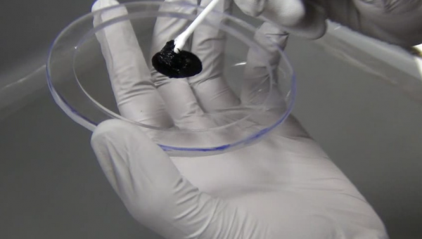
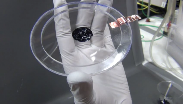
Painting the active area
 |
|
 |
|
|
|
 |
|
|
Save any leftover carbon grease and cotton swabs for step 4.
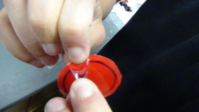
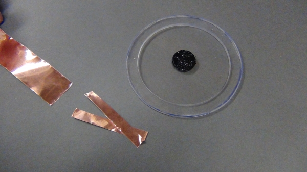
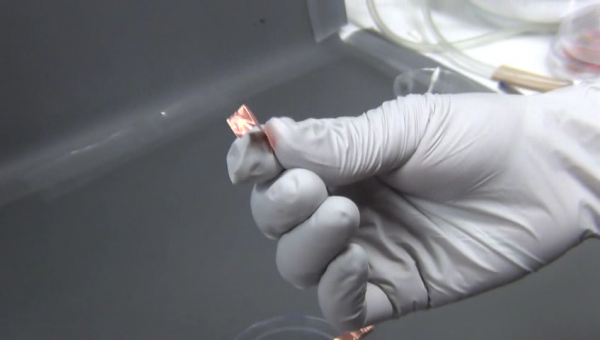
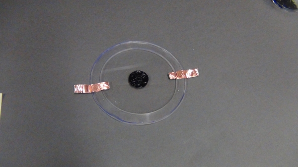
Step 3: Attach Copper Tape
In this step, short pieces of copper tape are attached on opposing sides of the active layer. The copper tape is folded over to allow attachment a high voltage amplifier later.
Fixing mistakes from Step 2
If some stray carbon grease found its way outside the active area during Step 2, simply choose that direction to attach the copper tape. Draw an imaginary line from the active area through the mistake and attach a strip of copper tape where that line intersects with the frame. A line of carbon grease will be painted right over the mistake in Step 4, covering it up.
 |
|
 |
|
 |
|
 |
|
|
|
 |
|
Step 4: Connect Active Areas to Leads
The last step involves connecting the active areas to the copper tape attached in the previous step.
|
|
|
Modeling
Maxwell Stress
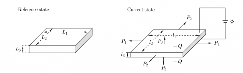
When a voltage is applied to a dielectric elastomer actuator, an electric field arises in the dielectric membrane. Generally this electric field is complex and its determination requires solving Maxwell's equations. However, when the membrane is thin enough, the active area can be modeled as a deformable plate capacitor.
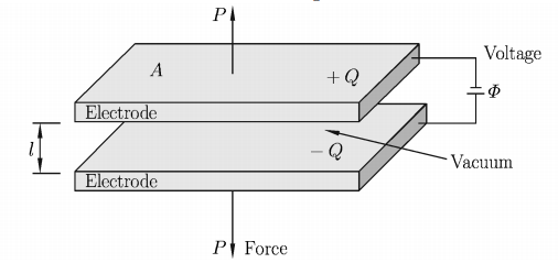
The electric field E inside a plate capacitor is
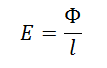
where Φ is the applied voltage and ℓ is the distance between plates in the plate capacitor. The electric field causes an effective compressive Maxwell stress
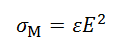
in the thickness direction of the membrane, where ε is the permittivity of the membrane. This Maxwell stress causes the active area to decrease in thickness and increase in area.
Modes of Failure
When testing dielectric elastomer actuators, various modes of failure have to be considered:
Mechanical Failure
Mechanical failure is one of the simplest modes to understand. When the membrane is stretched too much, the polymer chains tear and the material ruptures. If there are any pre-existing tears or notches in the material, this will lead to faster mechanical failure at those locations.
Electric Breakdown
When the electric field within the membrane becomes too high, the material can lose its insulating property. A conductive channel builds between the electrodes and burns a hole in the membrane. This phenomenon is called electric breakdown. It can be compared to lightning during a thunderstorm. When the voltage difference between a cloud and the ground becomes too high the air is suddenly conductive for a moment and lightening happens. See Testing section for a video of this.
Electromechanical instability
Electromechanical instability is a mode of failure that is critical for dielectric elastomer actuators. When an elastomer membrane is stretched only by a mechanical force, it behaves soft at low stretches but stiffens close to mechanical failure.
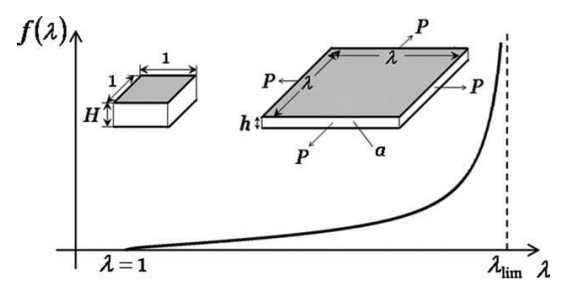
To increase stretch membrane one has to continuously increase the applied force. When the membrane is deformed by applying a voltage, the Maxwell stress is coupled with the thickness of the membrane. This means that the thinner the membrane is, the higher the electric field and therefore the higher then effective compressive stress applied to the membrane. This coupling can lead to a voltage-stretch curve shown below:
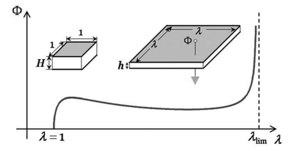
When the voltage is ramped up from zero, the elastomer stretches until the peak of the curve is reached. When the voltage is increased above the peak the actuator becomes unstable and jumps to a very large stretch on the right side of the curve. During this jump the actuator most of the time becomes so thin that electric breakdown occurs.
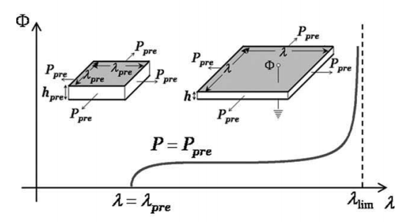
Prestretching of the membrane causes the peak to be moved to higher stretches or even be totally removed. For this reason we use a prestretched circular actuator in the fabrication section.
Loss of tension
When a prestretched dielectric elastomer actuator deforms, it often reduces its prestretch until it is completely lost. This can either lead to electromechanical instability and destruction of the material or to wrinkling of the material. Since the membrane is very thin it cannot sustain any compressive stresses from the sides (similar to a sheet of paper that wrinkles when you compress it in plane). When the actuator wrinkles it loses its function. See Testing section for a video of this.
Testing
High Voltage Safety
Depending on the size of your actuator, it can take many thousands of volts to see reliable actuation. For this reason, we insist you review your lab's safety manual on working with high voltages.
Always make sure your actuator is grounded before connecting any voltage source. The high voltage amplifier described in the Bill of Materials section will allow you to amplify a DC voltage source to the required level.
Example testing setup

In this testing setup, the actuator is suspended from above by a clamp and the electrodes are attached to ground (black wire on right) and a voltage source (red wire on left). The actuator was supplied with a square wave signal and the amplitude and frequency were adjusted until the actuator failed.
The following video demonstrates the actuator's response to increasing amplitude with a fixed frequency. In the video, the supplied voltage ranges from 5.4 kV to 7.0 kV, while the frequency of the square wave remains constant at 0.5 Hz. Enable annotations in the YouTube video for labels showing the timing of voltage changes.
In the next video, the signal frequency ranges from 0.5 Hz to 5.0 Hz, while the voltage supplied remains constant at 7.0 kV. The timing of when the frequency changes can be seen if you turn on YouTube annotations.
Loss of Tension
The actuator was then returned to a 0.5 Hz signal frequency and given an increased input voltage of 7.2 kV. At this point, the actuator began showing signs of loss of tension (as discussed in the Modeling section). The folds that appear in the active area are a clear indication of this:
Failure Mode: Electric Breakdown
The actuator continued to operate for another ~45 seconds before it fully failed through electric breakdown (as discussed in the Modeling section). The effect is very quick and can be hard to catch, but it happens around 13 seconds in this video, where you can see a little puff of smoke and the actuation stops:
Case Studies
General motivation for dielectric elastomer actuators
Interfacing with internal organs such as the brain, heart and lungs require a different type of electronics. Stretchable electronics will allow devices to interface with these organs without damaging them or otherwise impeding the natural state of the body. In addition they need to be able to withstand high frequencies and high voltages. Existing stretchable conductors are mostly electronic conductors such as carbon grease, microcracked gold film, serpentine-shaped metallic wires, carbon nanotubes, graphene sheets or silver nanowires. These existing conductors struggle with high frequencies, high voltages, biocompatibility, transparency and conductivity while undergoing large areal expansions, all of which are key tasks towards interfacing with the human body.
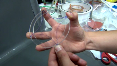
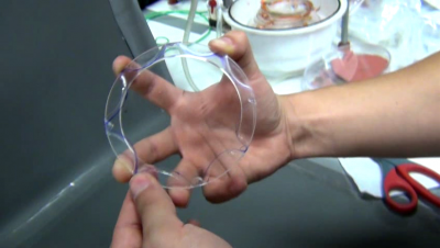
Case Study: Heart Shaped Dielectric Elastomer Actuator
As opposed to electronic conductors, many ionic conductors are biocompatible, are transparent and able to stay conductive at high areal expansions. Keplinger et al. (2013) designed a transparent large strain actuator consisting of a membrane of a dielectric elastomer sandwiched between two membranes of an electrolytic elastomer.
The team demonstrated this design by building a transparent heart shaped actuator using VHB 4910 tape as the dielectric and 100-um-thick polyacrylamide hydrogel containing NaCl as the electrolyte. The construction of the actuator is similar to the actuator described in this documentation. The dielectric was prestretched and attached to a rigid frame. Instead of carbon grease, the clear hydrogel is used for the active area.
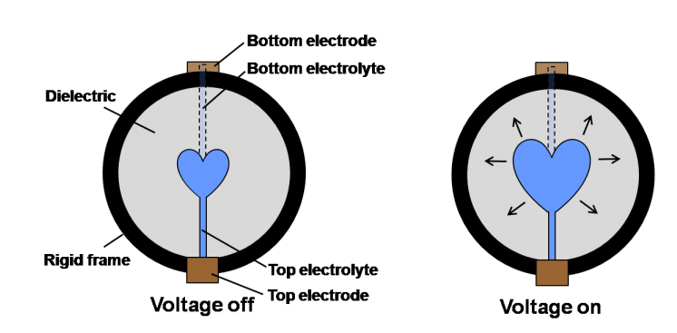

The attached video shows the actuator in action:
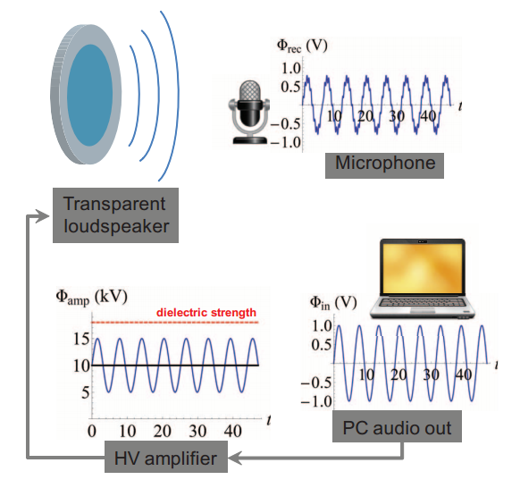
Case Study: Transparent Loudspeaker
To show how dielectric elastomer actuators are able to function at very high frequencies, Kepplinger at al. (2013) built a transparent loudspeaker that produces sound across the entire audible range, from 20 Hz to 20 kHz. The loudspeaker was used to play audio from videos played on a laptop. The audio from the videos was fed to the loudspeaker as an analog voltage signal through a high voltage amplifier from the laptop's audio output. The resulting audio was recorded by a webcam's microphone and compared to the audio source. For one test that involved giving the loudspeaker a 20-s test signal of constant amplitude and a linear sine sweep from 20 Hz to 20 kHz, the loudspeaker was able to successfully reproduce the main signal, with some inconsistency coming from vibrations of the actuator's frame, which was not optimized and began vibrating at its resonance frequency.
The video below shows the loudspeaker in action: