Combustion-Driven Actuators
Combustion-driven actuators (CDAs) are a class of soft actuators. They use the ignition of combustible mixtures (i.e. air-methane) to drive actuation. The Functional Material Laboratory at ETH Zurich has developed a fabrication technique for production of silicone monoblock structures (i.e. single continuous parts with no seams). These structures are both soft and able to withstand the high stresses imposed by combustion.
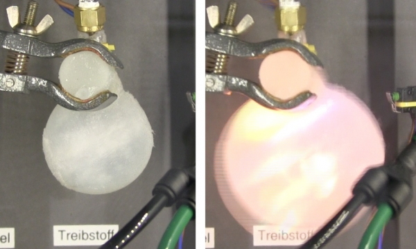
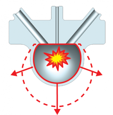
The basic idea of these actuators is similar to that of air pressurized systems. Instead of applying pressure to inflate channels, the expansion is created directly at the needed spot by igniting an air-methane mixture. The combustion process generates high energy gases which force the soft outer walls of the actuator to expand. The reaction energy is so large that the volume of the CDA can expand to several times its original size (for example the volume of the CDA presented in this documentation increases five-fold). The resulting motion is controlled by the usual variables such as geometry, material thickness or material choice (just as seen in PneuNets Bending Actuators).

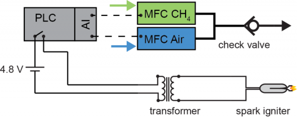
CDAs can be triggered by a simple control set-up, consisting of a programmable logic controller (PLC), mass flow controllers (MFC) and a spark transformer. Therefore, powering soft actuators with hydrocarbons not only enables direct conversion of fuel into work, but also reduces weight (i.e. energy density of hydrocarbons is higher than for Li-batteries). This has great potential for soft robots operating outdoors.
The CDA design presented in this documentation is only a demonstration of the CDA concept. This design is not used for actuation purposes directly. Nevertheless, the concept of producing monoblock actuators by casting virtual lost-wax molds is essential for ensuring long-term performance of any combustion-driven actuator design. The design of such molds is explained in the first part of this tutorial. Next, the fabrication process to produce the CDA that has been designed is explained. Using few equipment components, a CDA is then set up for control and testing in the next section. Possible applications for CDA are demonstrated in the form of case studies. Lastly, all files, including a detailed Bill of Materials listing all parts and materials needed to build the combustion-driven actuator designed in this documentation can be downloaded here.
| Some of the information contained in this web site includes intellectual property covered by both issued and pending patent applications. It is intended solely for research, educational and scholarly purposes by not-for-profit research organizations. If you have interest in specific technologies for commercial applications, please contact us here. |
Design
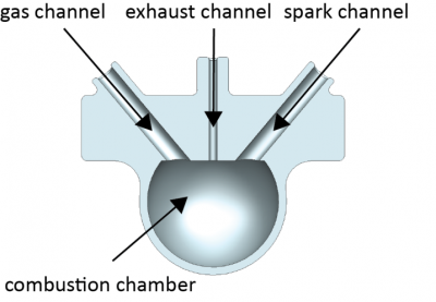
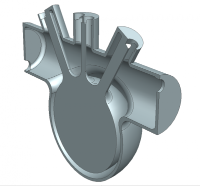
The combustion-driven actuator documented here consists of one single combustion chamber. This chamber has three channels to plug a gas injection nozzle, a spark gap (to trigger ignition) and an exhaust channel. This CDA is designed for demonstration purposes, so there is a horizontal cylinder that serves only as a handle to hold the soft actuator in position for testing. It can be seen in the picture below running perpendicular to the exhaust channel above the combustion chamber.
Upon a combustion event, the expansion will inflate the combustion chamber. Due to the chosen geometry of the CDA, the thin wall will stretch, while the thicker, horizontal section undergoes almost no movement (shown below). This repulsive motion can be extremely useful in robot design, where fast actuation plays a key point.
Combustions impose an incredible stress on the soft material. The first combustion driven soft robot presented by Shepherd et al. broke down after very few ignitions. One of the main reasons that robot failed was the use of two layers glued together to form the body. This revealed that a monoblock structure made from a single material is essential for combustion-driven actuators. This is why the main focus of this documentation is on the lost-wax mold design to produce these actuators.
The next two sections provide some background on material selecting criteria. Additionally we have a detailed tutorial on making the solid models of the actuator and the corresponding lost-wax-like mold using NX. The resulting part files as well as .stl files for 3D printing the lost-wax-like mold can be downloaded here. The part files include .stp formats for users of other CAD software, but we suggest following along with the tutorial in spirit and attempting to mimic the results in your own software.
Variation: Material
The material choice is much more important for combustion-driven actuators than for others. No company actually tests their silicones under simultaneous stress (i.e. thermal and mechanical). Therefore, silicone data sheets only tell half the story. However, we found several silicones that are able to withstand thermal and mechanical stress up to 30,000 combustion events. We'll start with some information about our selection criteria.
Selection Criteria
We use room temperature vulcanizing (RTV) silicones from Altropol GmbH*. They offer a wide range of two component silicone systems.
*Note: Like all of our guides, this was written by contributors from their own experience. Users in other countries may have to search for alternative suppliers.
The following points largely influenced our material selection:
- Handling Viscosity (HV) – Since we will later press the uncured silicone mixture inside our lost-wax-like molds, we need a mixture with a viscosity below 60 Pa·s (that of thick Maple Syrup). Otherwise, we need to apply larger pressures in order to fill the molds within the given handling time.
- Handling Time (HT) – The mold filling process takes, depending on the size of the mold, up to 80 minutes (for some silicones you will reach the handling time limit well before this). A rule of thumb from our experience: you need about 10-15 minutes per 100 cm3 including all preparation steps.
- Maximum Elongation at Break (MEB) – This value indicates if a material actually is able to withstand a combustion event. We suggest choosing a material with at least 500% MEB. Since thermal stress seems to decrease this value, a higher MEB would be preferred.
- Shore A Hardness (SA) – This value indicates weather a silicone is stiff (Shore A = 100) or very flexible (Shore A = 0) by measuring the depth of metallic cylinder being pushed into the surface with a force of 25 N. The higher the Shore A hardness the more violent the actuation.
Recommended Material Types
Condensation systems:
- RTV 1701 (HV = 22 Pas, HT = 80 min, MEB = 1000%, SA = 23)
Note: Condensation based systems will shrink with time. This is because the condensation product, a short alcohol, evaporates from the silicone.
Addition systems:
We achieved over 1,000 combustion events using the RTV 23 and over 30,000 for the RTV 1701. The exact handling of the presented silicone types is described in the fabrication section.
Lost-Wax Casting
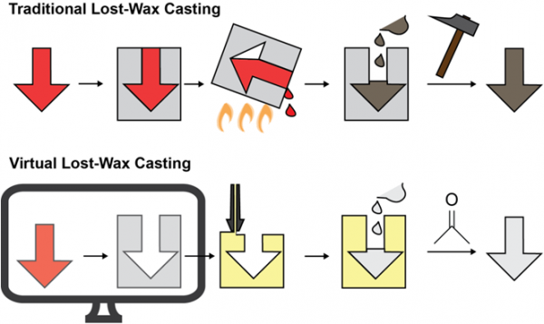
Lost-wax casting is a technique normally applied to cast metal. The process begins by producing a duplicate of the final part made from wax. This wax part is then placed in a box, which is filled with cement. After curing, the cement block is heated up and the wax melts and pours out. The remaining cement is now a negative of the final part. This negative mold is then filled with melted metal. After cooling, the cement mold is destroyed and removed, leaving a cast metal part.
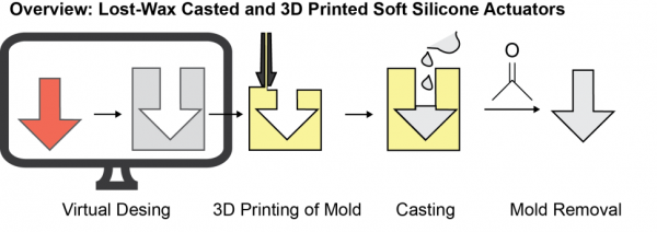
Virtual lost-wax casting
Our fabrication process uses the same casting idea but uses other materials than metals. We virtually design a part and then create a virtual mold by inverting the part design (see Computer Aided Actuator Design). This mold is then 3D printed and filled with uncured silicone. After curing, we destroy the mold by dissolving it in solvent.
Computer Aided Actuator Design
We designed this actuator using the computer aided design (CAD) software Siemens NX. The following short tutorial shows how to design such a combustion driven actuator. Note that other CAD software (i.e. SolidWorks, Inventor, AutoCAD,…) can be used, but this tutorial is specifically for NX software. The main reason to use NX is its simplicity in creating free forms. This might be helpful especially if you want to design complex geometries. If you do not have access to NX, we encourage you to follow along through the guide to understand the design process in principle and even to attempt to replicate our design in your own software of choice. Downloads of the part files for the actuator design in this tutorial can be found here which include formats compatible with most CAD software.
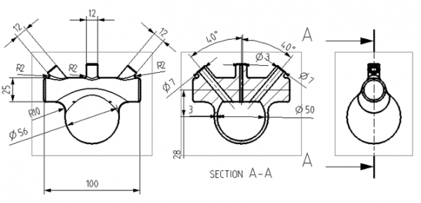
In the following sections, we show you how to create the simple combustion driven actuator shown below. All necessary sizes are indicated in the figure below. The design is comprised of a cylinder, which partially drives through a hollow sphere. Three channels, aligned at different angles towards the sphere center, form the gas inlet, exhaust and igniter electrode connection.
Again, all part files can be found here.
Step 1: Rough Design
Begin creating the part
- Start by creating a new model file in NX. (File → New: Choose Model/Modelling).
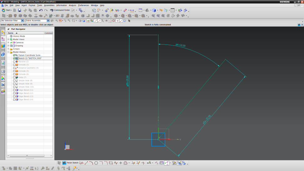
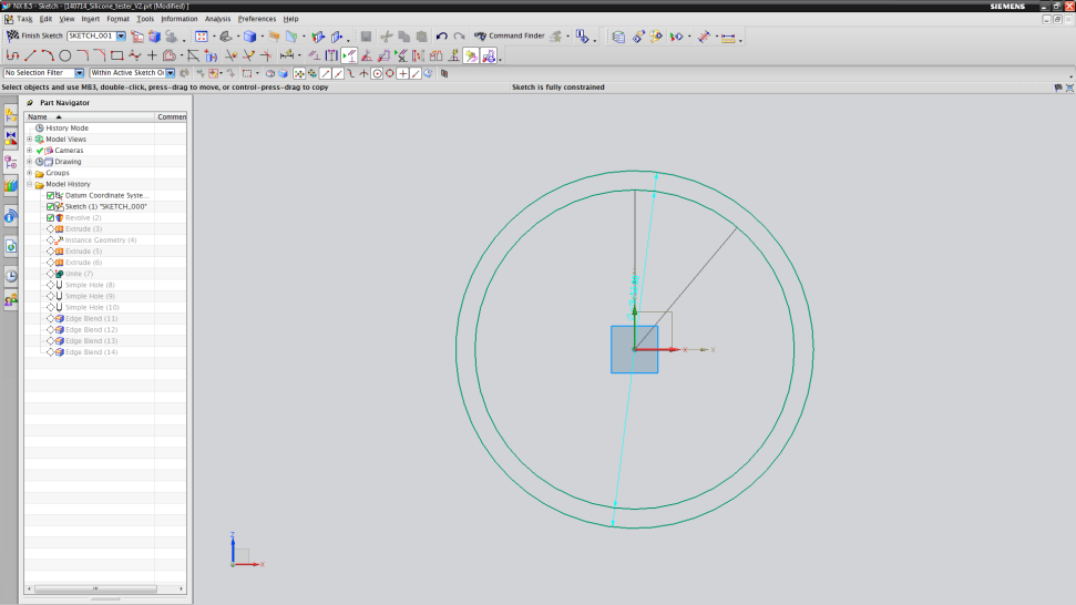
- Then, make a new sketch drawn in the XZ-plane (Insert → New Sketch: choose XZ-plane with your mouse).
- Draw two lines 25 mm in length, starting at the origin. The angle between the lines should be 40°. These lines will help to align the channels in later steps.
- Lastly, click on “Finish Sketch” located in the bottom toolbar.
Design the combustion chamber.
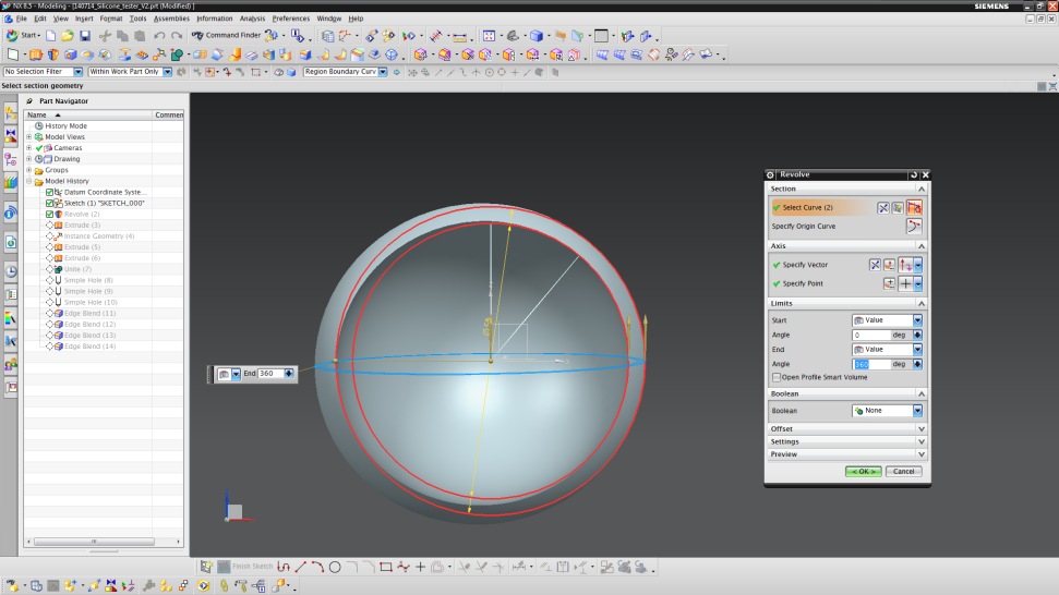
- Insert a revolved part (Insert → Design Feature → Revolve).
- Click on the “Sketch Selection” item in the new “Revolve” menu. A new sketch should appear. Choose the XZ-plane again.
- Now sketch two circles (Insert → Curve → Circle) with origin (0,0) and diameters of 50 mm and 56 mm, respectively.
- To go back to the "Revolve" menu, click on "Finish Sketch" again (the button is in the upper left corner now).
- Then choose the vector to be the Z-vector (should be blue) and the point to be the point of origin.
- The angle should start from 0° until an angle of 360°.
- Finalize by clicking on OK.
Add channels
- Hide the hollow sphere by right-clicking on the “Revolve (2)” item in the part navigator (left panel). Choose “Hide” and the sphere is now hidden.
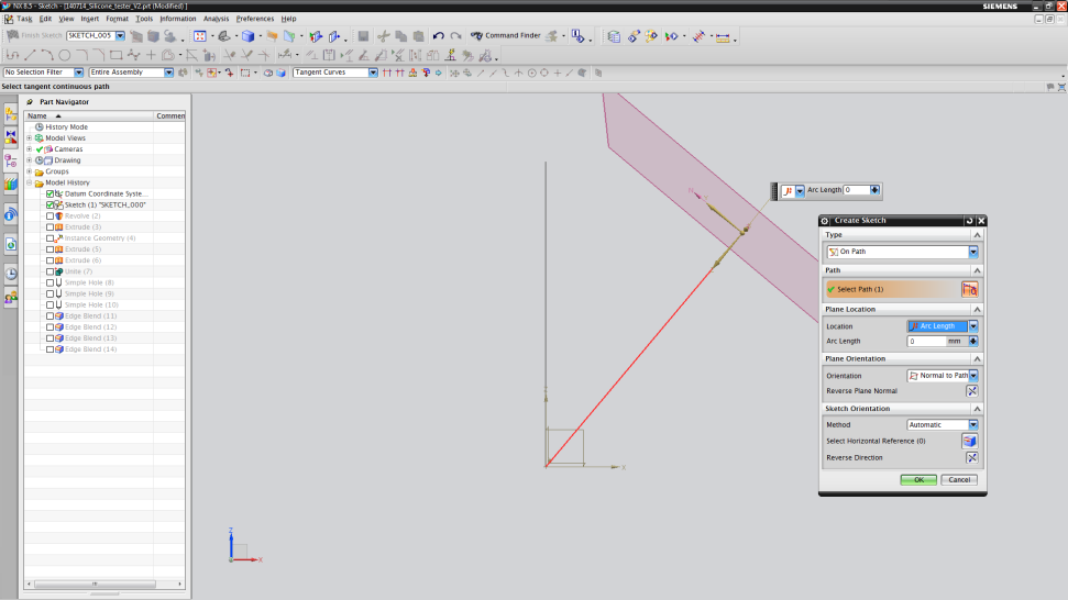
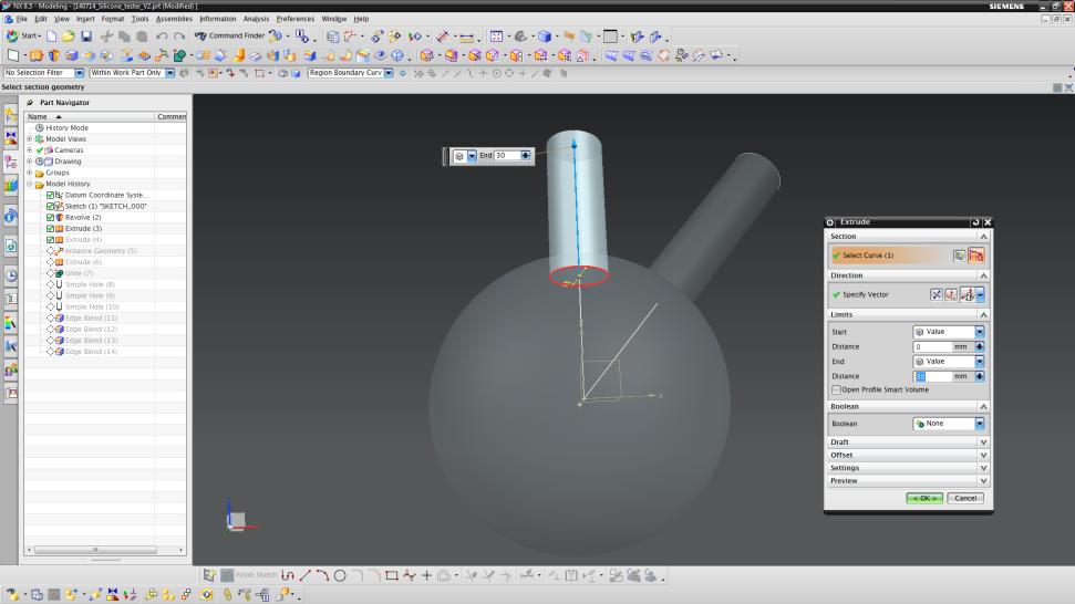
- Insert an “Extrude” part (Insert → Design Feature → Extrude).
- Click on “Sketch Selection” item in the “Extrude” menu. A new window (“Create Sketch”) will open. In the type section, choose "On Path".
- Then choose the sketch-line at 40° drawn before. Set "Arc Length" to 0 mm and click "OK". The view will now turn.
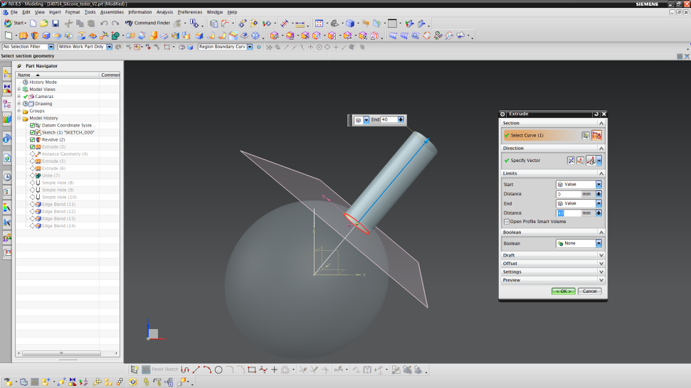
- Draw another circle with origin (0,0) and a diameter of 12 mm.
- Click on “Finish Sketch” after you are done.
- Choose a specific vector. In our case, it is the "Face/Plane Normal".
- Set start and end distance to 0 and 40 mm, respectively.
- Finalize by clicking "OK".
- To create the middle channel, repeat the steps used to create the first channel.
- This time, choose the guide line perpendicular to the sphere.
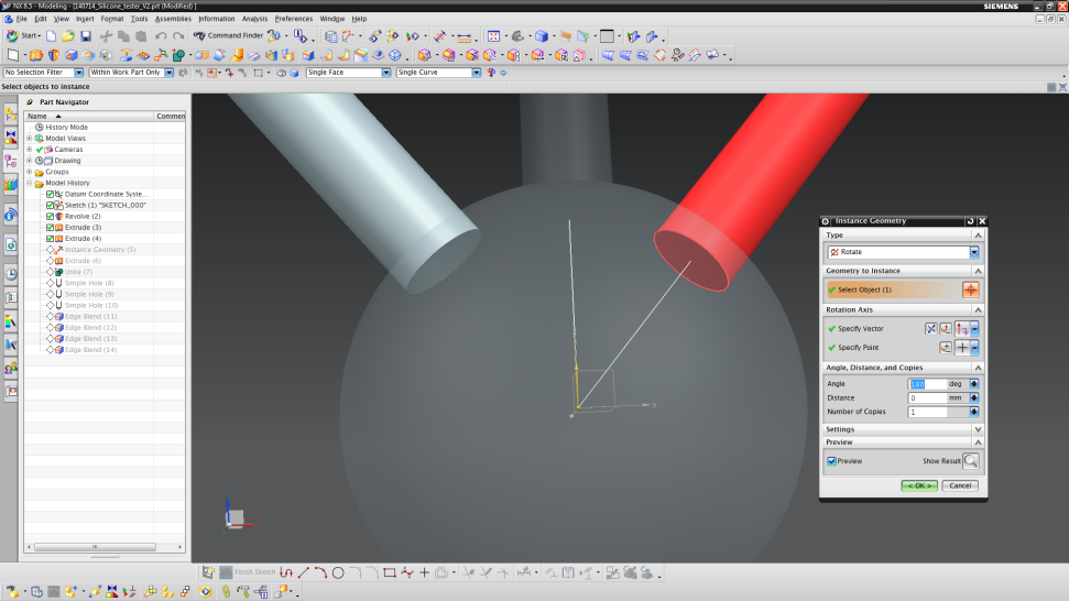
- To make the left channel, we can just create a mirrored copy of the right channel.
- Copy the geometry (Insert → Associate Copy → Instance Geometry).
- Click on Select Object and then choose the cylinder at 40°.
- Specify the vector to be the Z vector (vertical axis) and the point to be the point of origin.
- Set the "Angle" to 180° and the "Number of Copies" to 1.
- Finalize by clicking on "OK".
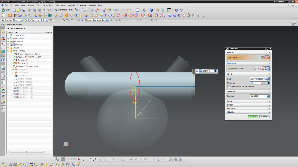
Add horizontal cylinder
- Add another "Extrude"-part.
- Choose the ZY-plane for the sketch.
- Now sketch a circle with an origin of (0,28) and a diameter of 25 mm.
- Finish the sketch to return to the "Extrude" menu again.
- In the "Limit" section choose "Symmetric Value" and enter 50 mm.
- Finalize by clicking “OK” again.
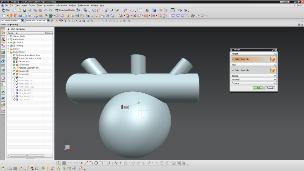
Unite
- Unite all parts (Insert → Combine → Unite).
- Select all parts and finalize by clicking "OK".
Step 2: Holes & Blends
Add channel holes
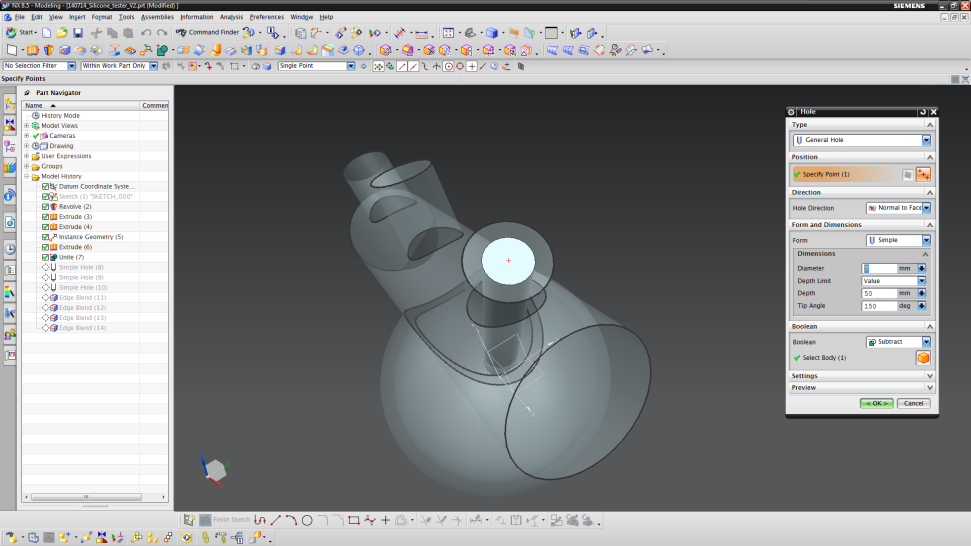
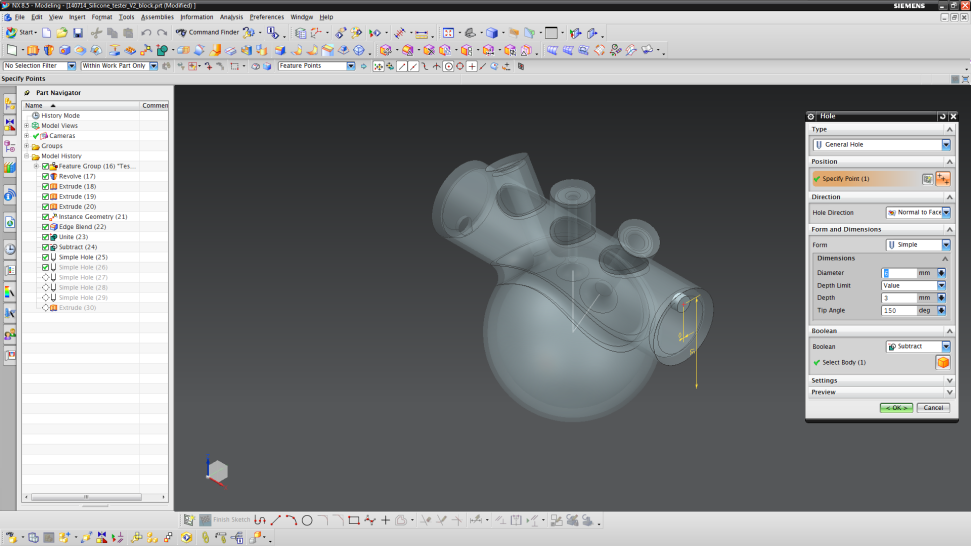
- Now, we build the holes into the cylinders to get our channels (Insert → Design Feature → Hole).
- Zoom in on one channel as shown in the image below and choose the edge of the extruded cylinder.
- The edge should be highlighted in yellow.

- Now enter the data for the channel.
- Set the “Diameter” to 7mm, the “Depth” to 50 mm and the “Tip Angle” to 150°.
- Finalize by clicking “OK”.
- Repeat this process for the left channel.
- The middle channel uses the same procedure, but with a diameter of 3 mm.
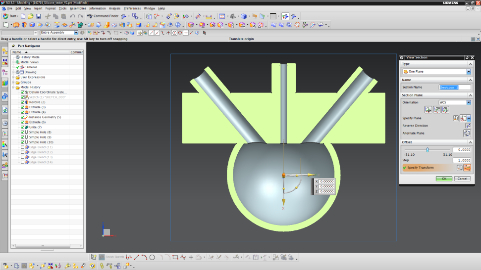
- To check whether your channels penetrate into the combustion chamber or not, use “Crtl+H” to open the “View Section”.
- Choose the YC-orientation and click “OK”.
- Now, your actuator should look like the figure below. If so, exit the “View Section” (View → Section → Clip Work Section)
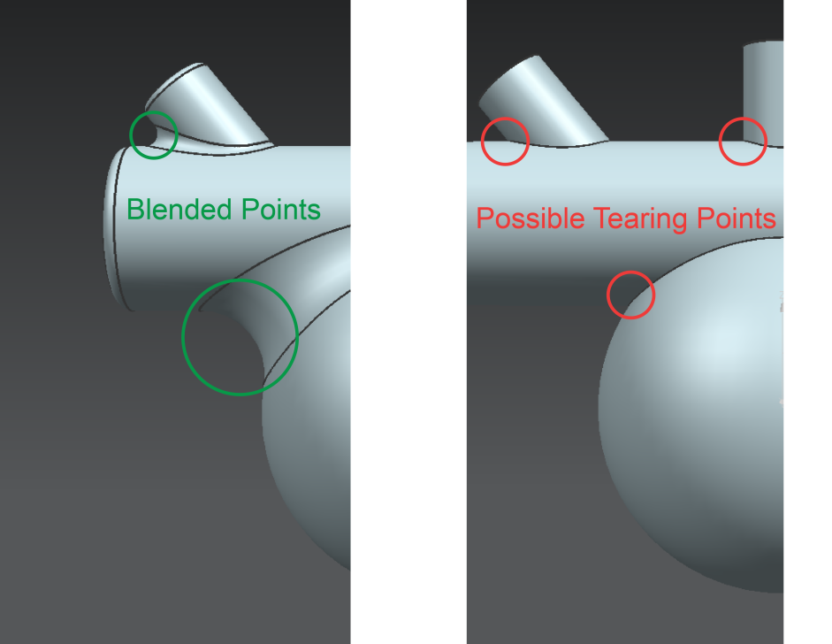
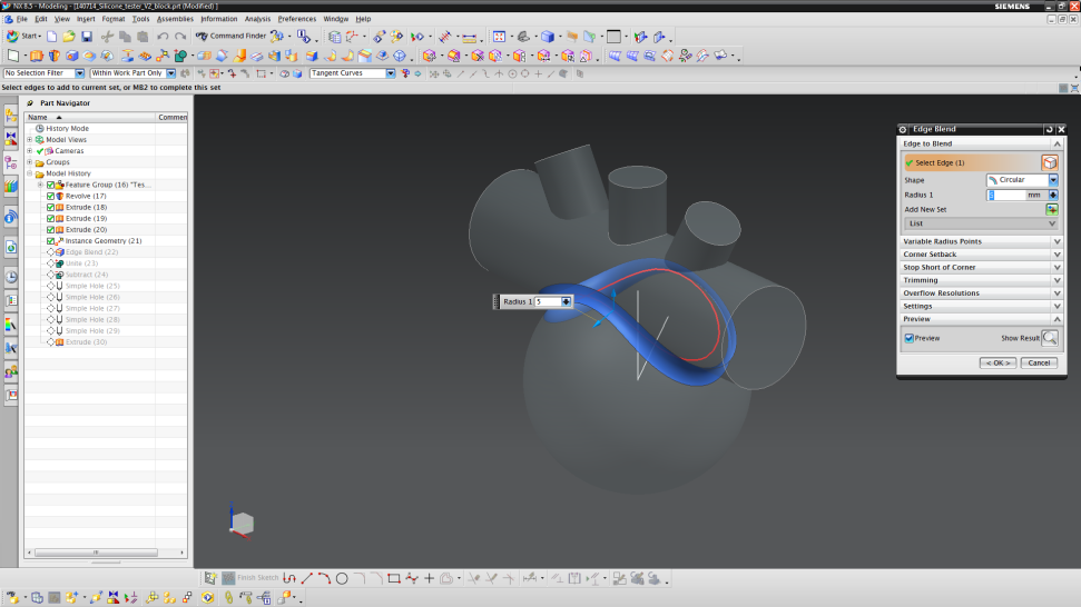
Add edge blends
- Now, we add edge blends in order to smooth the surface.
- This is important, since the silicone has a higher chance to tear where there is an incisive angle.
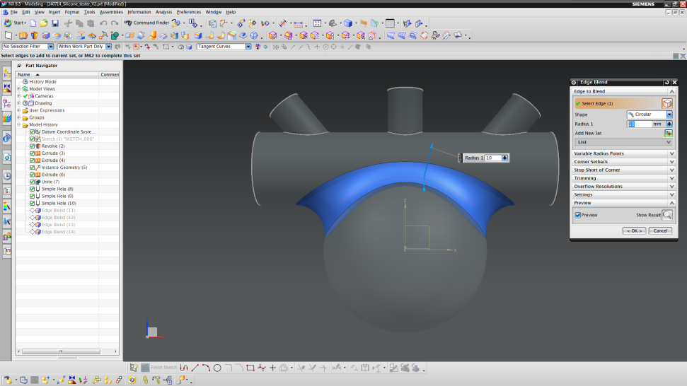
- Insert a blend (Insert → Detail Feature → Edge Blend).
- Choose edge separating the horizontal cylinder from the combustion chamber.
- Choose a radius of 10 mm.
- Finalize by clicking “OK”.
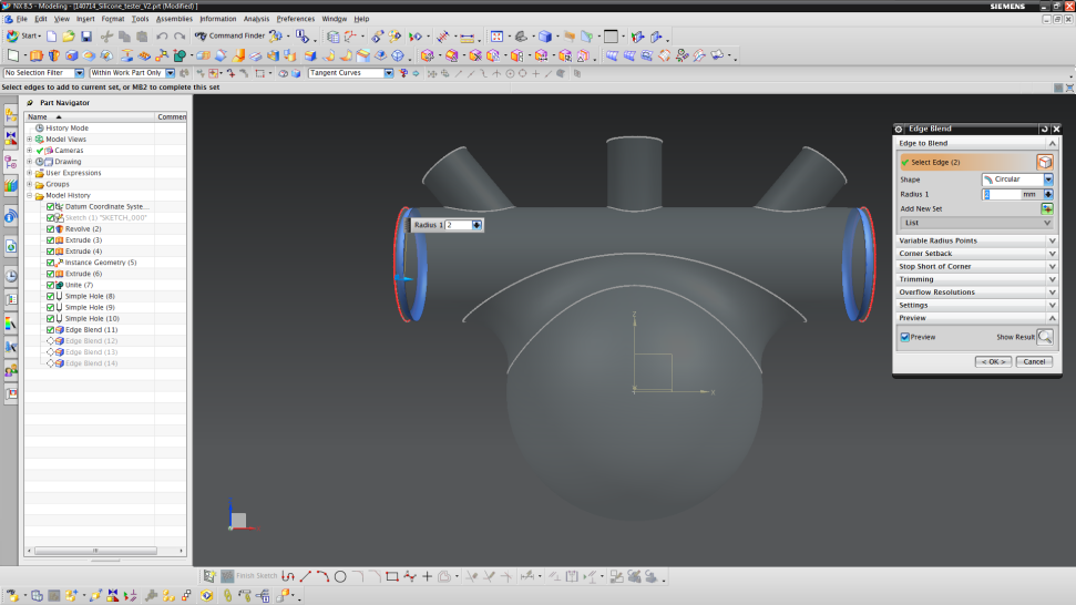
- Select the two edges shown below and use a radius of 2 mm.
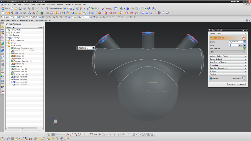
- Select the edges shown below and use a radius of 1 mm.
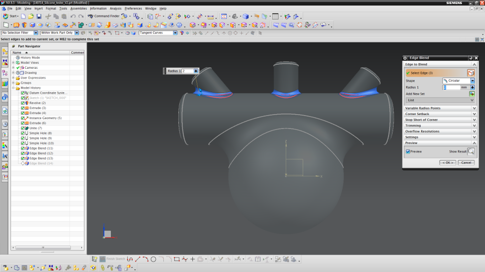
- The edges shown below should also have a radius of 2 mm.
- Finalize again by clicking “OK”. You now have designed your combustion driven actuator.
Step 3: Mold Design
Designing the mold
Now that the actuator has been designed, we need to make the mold that will allow us to cast the part. To do this, we will "invert" the design from the previous steps. This inversion process essentially involves making a part that has the same shape, but with slightly larger dimensions in order to enclose the actuator design and then subtracting the actuator design to create a hollow mold. We then have to add filling and venting holes to allow silicone to enter and air to escape the mold during casting. This section will detail how to create the basic mold for the actuator designed in those previous steps.
Note: The minimum wall thickness of the mold should be 1.5 mm. Otherwise, your 3D printer might not be able to successfully print the mold. Also, the silicone filling becomes quiet difficult in terms of leaking spots.
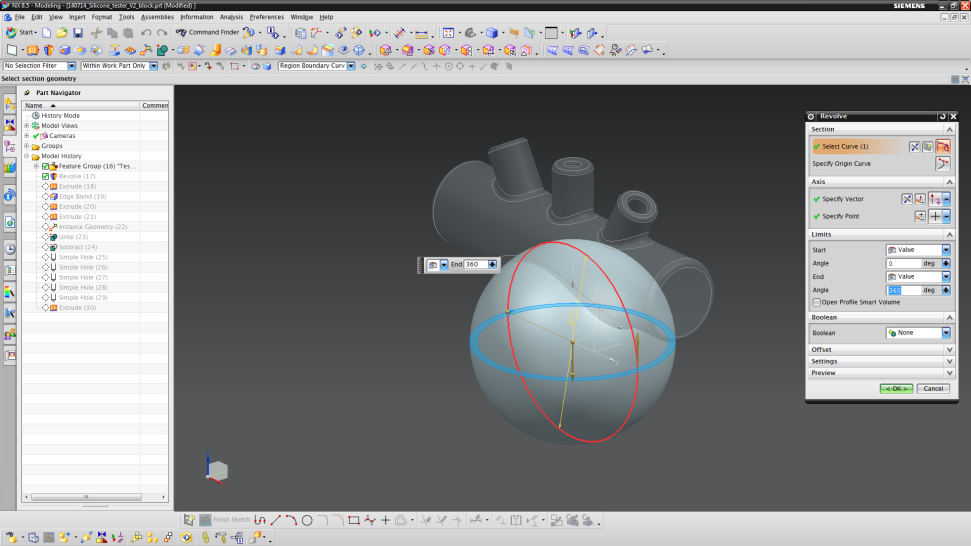
- Start by inserting a “Revolved” part (Insert → Design Feature → Revolve).
- Choose the ZX plane to draw the sketch.
- Sketch a circle with origin (0,0) and a diameter of 59 mm.
- Set the limits from 0° (start) to 360° (end).
- Next, add another “Extruded” part (Insert → Design Feature → Extrude).
- Choose the ZY-plane for your sketch and sketch a circle with origin (0,28) and a diameter of 28 mm.
- Unite the two parts by selecting the “Boolean”-setting to “Unite”.
- Like in Step 1, we now build the mold parts for the channels.
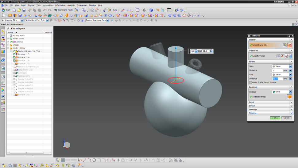
- Create an “Extruded”-part (Insert → Design Feature → Extrude) and set the sketch plane to the vertical orientation line (the sketch plane should face vertically) and draw a circle (origin (0,0), diameter 15 mm).
- Extrude the circle from 0 to 31.5 mm along the Z-axis.
- Unite the cylinder with the remaining parts by choosing “Unite” in the Boolean part.
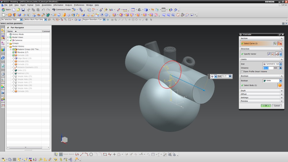
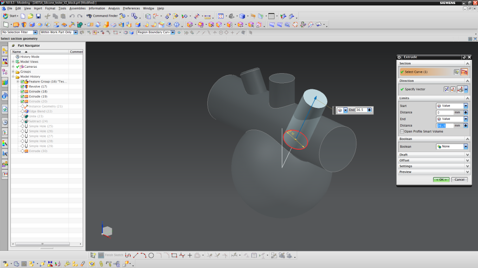
- For the sloped channels, extrude (Insert → Design Feature → Extrude) a cylinder from a circle sketched at origin (0,0) and a length of 36.5 mm along the sloped orientation line.
- Do not unite the cylinder with the remaining parts in the Boolean setting this time.
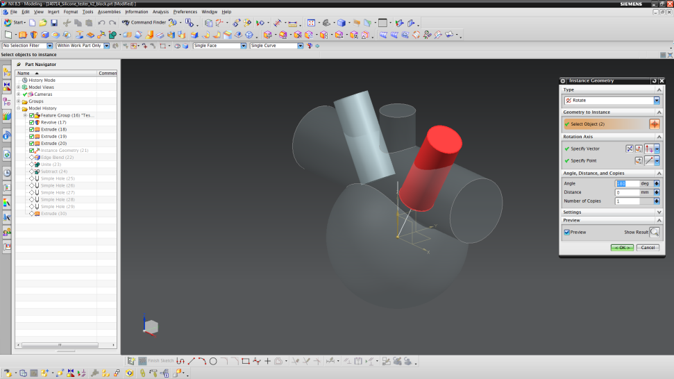
- Copy the cylinder as described in Step 1 (Angle = 180°, Number of Copies = 1).
- Blend the connection of the sphere and horizontal cylinder as shown below. Choose an edge blend radius of 5 mm.
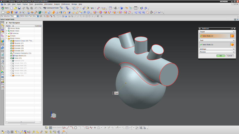
- Unite all mold parts designed in Step 3 using the “Unite” tool (do not include the actuator design from steps 1 and 2).
- Afterwards, subtract the actuator design from the mold to get the inverted design (Insert → Combine → Subtract).
Dead volumes
One of the main problems when creating and filling a mold are dead volumes. These dead volumes can trap air and therefore destroy your design upon filling uncured silicone. Hence, the design not only has to be “inverted” to form the mold but also specific connections (in the form of vented holes) to the outside have to be made. The vented holes enable the escape of air, in order to allow silicone to fill the pockets that would otherwise be filled with this trapped air. Our design needs four of these vents, which are all positioned at the end of a channel inlet.
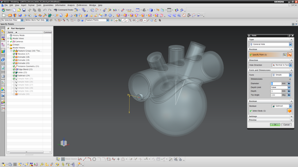
Add all necessary filling and vented holes by adding holes into the hollow mold
- We first make the holes that will be used to fill the mold with uncured silicone.
- Begin the process by inserting a hole (Insert → Design Feature → Hole).
- The first hole is set on one of the faces of the horizontal cylinder.
- The center of the hole should have coordinates of XC = 0 mm and YC = 18 mm.
- Specify a diameter of 6 mm, depth of 3 mm and a tip angle of 150°.
- The next hole will be on the opposite face of the horizontal cylinder.
- This time, the hole should be at XC = 0 mm and YC = 37 mm.
- Use the same hole dimensions as before.
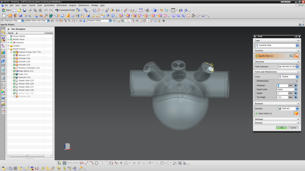
- Now, we will make the vented holes.
- Insert another hole and choose to sketch on one channel top.
- The point should be at XC = -3.5 mm and YC = 0 mm.
- Use the same hole dimensions as for the horizontal cylinder.

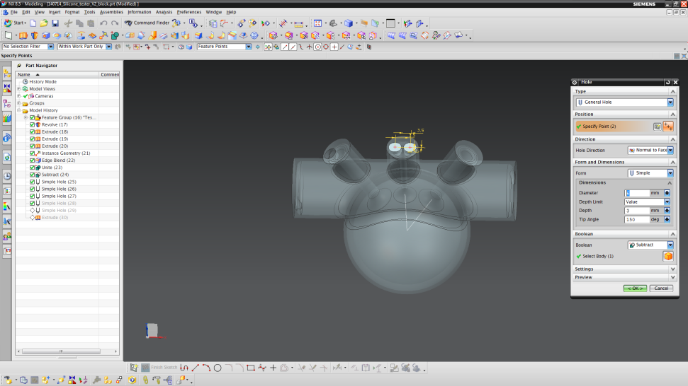
- For the vertical channel, we will make two holes.
- Insert another hole and choose to sketch on the top face of the middle channel.
- The two points have to be on the same horizontal line (XC1 = -3.5 mm / YC1 = 0 mm and XC2 = 3.5 mm / YC2 = 0 mm).
- Use the same dimensions as before.
- The last hole should be designed on the remaining channel top surface at the point XC = 3.5 and YC = 0 mm. Continue to use the same dimensions for the hole.
- Now, your mold should have an interior as shown in the beginning of Step 3.
- To see the cross section, press “Crtl + H” and choose the YC plane.
Fabrication
This section contains a detailed description of the fabrication process to manufacture combustion-driven actuators (CDA). One of the key features to produce lost-wax casted soft silicone actuators is 3D printing. We therefore explain in more details the principle behind this technique, the importance of the printed polymers and highlight the resulting advantages. We additionally explain the casting and mold removal processes. A detailed Bill of Materials listing all parts and materials needed to fabricate the combustion-driven actuator shown in this documentation can be downloaded here.
Process Overview
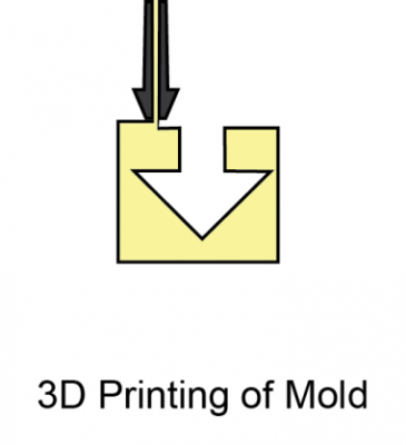
| 3D Printing the Mold: After the mold design (see Computer Aided Design section) is established, the data gets processed and loaded into 3D printing software. This software then produces an operation chart, enabling the 3D printer to print the mold. |  |
| Casting: After post-treatment of the 3D printed mold (more details are given in the relevant subsection), a mixture of uncured silicone and its necessary crosslinking agent is pressed inside the voids to cast the mold. | 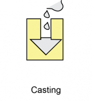 |
| Mold Removal: The mold around the cured actuator is then removed by dissolving the mold polymer in a solvent. This process frees the final actuator and produces the previously mentioned and very important monoblock structure. | 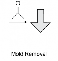 |
3D Printing the Mold
 3D printers belong to the class of fused deposition modelling (FDM) devices. They build parts layer-by-layer by melting model or support polymer wire inside a hot fuse which is then extruded onto a platform and cured on the fly. Our system uses acrylonitrile-butadiene-styrene (ABS) co-polymer for the model and polylactic acid (PLA) as support material, but similar systems with different materials will work just as well to make the mold. The only caveat is that the model material must be dissolvable in order to remove the cast actuator once it is set. More details are given in the Mold Removal section.
The printer software calculates the tool path from a triangulated surface file of the CAD model (usually an .STL file). The 3D printer cannot print material on air, so support structures are used to build a printing platform and to fill any voids. The model material layers then build the actual part on top of the support material. The support structures can now be removed, leaving only the model behind. We used the following printers to make this actuator mold:
CAD File conversion
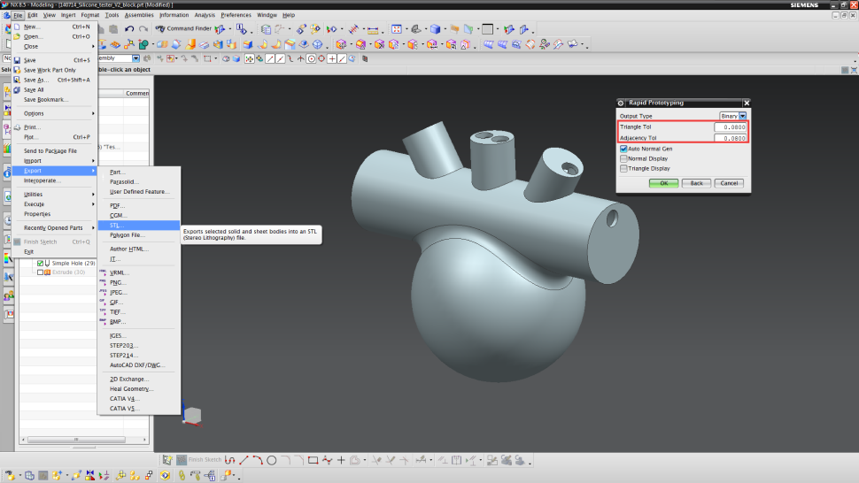
First, the CAD part-file has to be exported into .stl (File → Export → STL). This file format delivers the necessary triangulation for the 3D printing software. In the red square, important exportation parameters are highlighted. The lower this value is, the larger the file size will be, but also the better the input resolution of the mold. We suggest to use a triangle resolution and an adjacency tolerance of 10-3 at least.
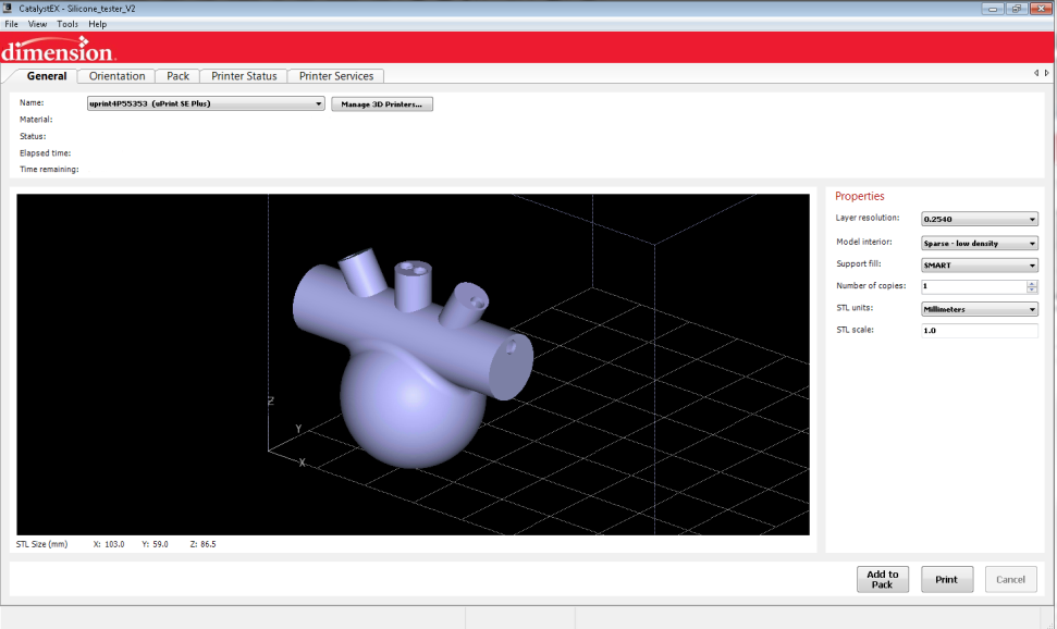
Set-up 3D Printer
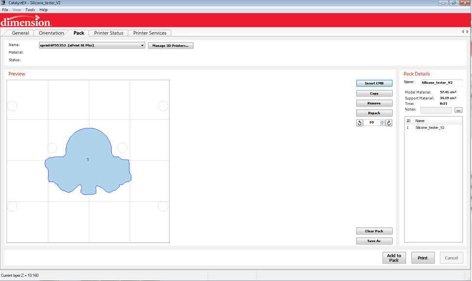
The .stl-file now can be loaded into the 3D printing software (File → Open STL). Choose the layer resolution to be 0.254 mm and set the model interior to “Sparse – Low density”. We want the mold to be easily dissolvable in later steps, so having a low density will allow solvent to penetrate the mold easier. Then, click on the “Orientation”-tab (upper left).
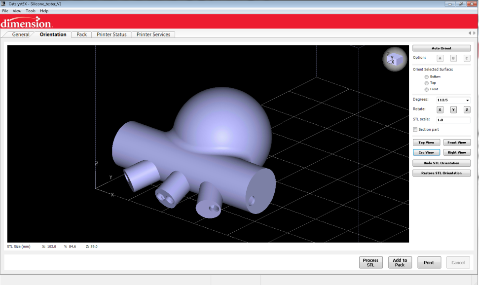
Depending on the positioning of the model part, more or less support material is needed. Therefore, the part needs to be turned to minimize the material need. Turn the part by entering 112.5 degrees into the corresponding field and click on “Rotation:X”. The part now turns. Then click on “Add to Pack”. The software will now calculates all tool paths.
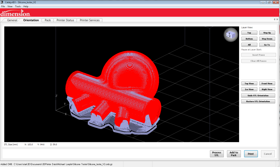
All tool paths are shown (red for material, purple for support tool path) after the completion of the calculations. Now, verification is needed. The mold has an inner sphere (representing the combustion chamber), which is connected to the three cylinders (representing the channels). There has to be a connection to the outer mold shell, otherwise the interior geometry is not set in place correctly (loose parts inside). To verify this, click on “Top View” to change perspective and choose the displayed layer to be “Top”.
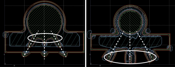
By pressing “Page Up” or “Page Down” on the keyboard, one can switch within the layers. Go down. You will reach a layer where suddenly, the spherical combustion chamber has three extruded fingers (left picture). As you continue down the layers, these fingers move along the dashed lines until they reach the outer mold shell (right picture). Thus, this design has a connection between the inner geometry and the outer shell.
Next click on the tab labeled "Pack" (upper left). Here, the positioning of the parts can be performed. This is especially interesting, if you would like to print the actuator mold several times. On the right side, details on your model and support material consumption, as well as the estimated printing time are given. Click “Print” to start. Then follow the instructions given on your 3D printer.
The Printing Process
The printing process is very reliable and robust. Nevertheless, a few things you should remember when using these 3D printers:
- Platforms can be used several times. After a while, adhesion of the first layer is reduced and a part can peel off (creates a huge mess inside your printer and may damage your fuse head). Therefore it is advisable to use new platforms for large molds.
- Calibrate X,Y and Z-axis periodically. This helps to give you stable printing performance. Also check whether your fuse has any polymer deposits nearby. These might interfere with any freshly printed layers.
- Humidity affects your printing. Therefore store everything in a dry environment. Unload all materials, especially if you do not print for several weeks.
Mold Post-Treatment
The mold has to be washed in an alkaline bath to remove the support structure (base catalyzed degradation of PLA). This process can be sped up by heating to 60°C and introducing convection by a circulation pump. Also, specific flushing of the mold helps to dissolve the PLA. Once the support material is dissolved and washed away, the CDA mold is then dried and can be prepared for the casting process.
In principle, any model/support system can be used to print molds. The important step is the mold dissolution. If a solvent does not dissolve the model material, the casting technique does not work. More details are given in the section: Mold Removal.
Casting
 The casting process to build a combustion-driven actuator (CDA) with a necessary monoblock structure consists of three steps. First, the mold has to be prepared by connecting casting parts. Then, the silicone has to be mixed. Last, this mixture is injected into the mold and cured. Even though these steps seem to be simple, we will show a few tricks to increase your casting efficiency. Some of the preparation steps are also illustrated in the video below.
Mold Preparation
The mold we've created needs a few additional parts prior to casting. These parts will further help to prevent any dead zones, which would trap air (other preventive steps are explained in Step 3 – Mold Design).
- First, the mold has to be fixated using a clamp. The orientation of the mold needs to be in such a way that air can easily escape trough the vented holes we created earlier or through the reservoir.
- Then, tubing is glued onto each of the vented holes. We use silicone tubing and hot glue for this step.
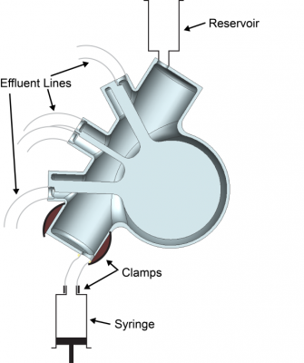
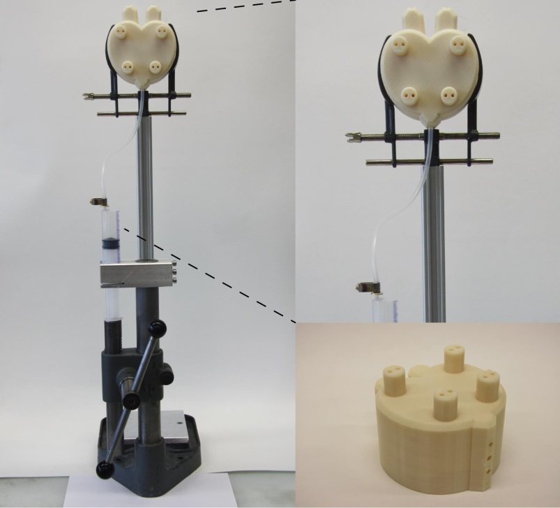
- A reservoir for uncured silicone is installed on top. Since uncured silicone is likely to diffuse into the porous first mold layer as the actuator cures, this material pool helps to keep the mold filled until complete curing. This can be made of an empty syringe, glued on top.
- Last, the injection line has to be installed. We again use silicone tubing for this step. Silicone is later filled into syringes and injected by an in-house made hand press (a picture of this press is shown further down this page). One syringe cannot hold all of the silicone needed to fill the mold. Therefore, a fast connector is needed to exchange empty syringes with full ones. This connector is made of a metallic hull inserted into the tube and then tightened with a clamp. (See video below for details).
Silicone Mixing
Mix silicone according to the instructions given by your manufacturer, in our case Altropol (usually given at the end of each data sheet). Each system has its own monomer to cross linker ratio. Mix until a homogeneous material is obtained, either by hand or with a mixer. We also suggest you degas the mixture to decrease the amount of dissolved air. This helps to avoid entrapped air in the molds.
Injection
The figure below shows the previously mentioned silicone press (taken from Schumacher et al.). The syringes (50 mL) are filled with the uncured silicone mixture and then injected into the mold until the reservoir is full. When a tube connected to a vented hole starts to fill with silicone, a possible dead zone has been completely filled with silicone and that escape route is no longer needed. You can inject hot glue into the tubing to seal it so no more silicone escapes. (This technique is shown in the video below).
A few tricks:
- Do not put too much force on the press. This creates pressure peaks and the injection line may burst or the syringe can break down.
- Heat-shrink tubing can support silicone tubing in critical flow regions (i.e. at the injection site)
Mold Removal
 Once we have the mold with fully casted and cured silicone, we need to remove the mold. Unfortunately, because of the monoblock structure of the actuator, we cannot simply open the mold and release the actuator. We must destroy the mold and the most effective method is to choose a mold material that is strong enough to hold up to the molding process, but is also soluble in certain liquids. We have chosen ABS because it is soluble in acetone, so we can simply dissolve it away.
- Put the molds containing cured silicone into a bath of acetone.
- After a while, the dissolving process has advanced in such a way that one can peel off the outer shell. The inner ABS structures will need more time.
- One can accelerate the dissolving by slightly pulling away the silicone wall from the structure, with a spatula for example. Then, the gap created between the ABS and silicone can be filled with acetone. Another possibility is to inject acetone directly into the inner mold.
- Due to the low density printing, there should be enough voids to fill. If enough acetone has entered the mold material, the dissolving will take much less time.
Control & Testing
This section shows how to setup the produced combustion-driven actuator (CDA) for testing. This involves connecting the actuator to fuel lines and the necessary control hardware. As mentioned earlier, only a few extra parts are actually needed. A detailed Bill of Materials listing all parts and materials needed to build the combustion-driven actuator designed in this documentation can be found here.
Setup
To setup the CDA you have created, you will need three additional components:
- Spark igniter with a spark gap of a few millimeters
- The spark igniter is produced by skinning (stripping) two copper wires. They are put into different Teflon tubing for insulation purposes and filled with the same silicone mixture. This produces a simple but very robust igniter. The figure below further describes the manufacturing process of these spark leads.
 Click here for larger image
- Exhaust tube
- The exhaust tube should have a smaller diameter than the injection nozzle. This guarantees a higher backpressure which will result in a higher combustion. Alternatively, valves could be used to actively control closing and opening times of the combustion chamber.
- Injection nozzle
- The injection nozzle should have a check valve. This valve closes upon a combustion event to prevent back pressure from the fuel lines which also increases expansion of the CDA. Such valves can be purchased from Parker / Legris.
The spark igniter is then connected to a spark transformer. This spark transformer will take a 5 V input and step it up significantly so you can get a reliable spark from your igniter. Code running on the programmable logic controller (PLC) can then close the relay at desired intervals to control the ignition sparks. We use PLCs from Siemens (Logo) in this documentation, but Arduinos (as used in many other guides in the toolkit) are an equally good option to control ignition. The PLC controls gas flow as well by addressing two mass flow controllers (MFC), purchased from Vögtlin. The protocol we used in this demonstration can be downloaded here.

Testing
To test the CDA, the following parameters were used:
- Methane flow rate: 0.4 – 0.6 L/min
- Air/Methane ratio: 10
- Inlet pressure air/methane: 2 bar (required by the listed MFC’s)
- Ignition frequency: 0.5 Hz
The PLC uses an analog signal in order to control the amount flowing through the MFCs. This signal varies within a range of 0 to 10 V, corresponding to an analog value of 0 to 1000. Therefore, one has to devide the maximum analog value (AV) by the maximum flow rate (FR) and multiply times the desired flow rate to convert the desired flow rate to an analog value for the PLC. An example:
This value now can be entered at the designated position in the protocol (shown below).
The final result is a combustion-driven actuator, able to increase its volume five-fold after less than half a second. Only a few equipment parts are needed in order to operate such an actuator. The concepts presented here can be used in many ways. For instance, the volume increase can be used to power soft pumps, which is shown in the case study section.
Case Study
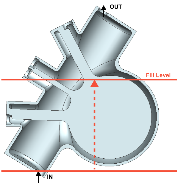
This case study highlights how the previously mentioned concepts of combustion-driven actuators (CDAs) can be applied in order to power a pump. This is done by using the expansion of the combustion chamber in order to squeeze an adjacent pump chamber. Soft pumping has the advantage of conveying liquid without the need of any bearings. Due to the physical separation of combustion and pump chamber, fluids containing solid fragments (i.e. sand or stones) can be transported without any severe internal pump abrasion.
Combustion-driven Soft Pump
Figures and videos are taken from Schumacher et al.
 The figure on the right shows the design of a pump chamber with an adjacent combustion chamber, as mentioned in the above paragraph. Schumacher et al. analyzed the following behaviors of the designed pump:
- Expulsion rate at different fill levels (0 cm to 80 cm)
- Thermo stability of the soft pump at different ignition frequencies
- Surface damage upon combustion
- Pumping under deformational stress
This design lasted for 10,000 combustion cycles. Schumacher et al. were able to show that pumping was still possible even though the pump was exposed to severe mechanical deformation (see the video below for more details). The overall energy efficiency was determined to be 0.03%, which is not acceptable for practical applications. Nevertheless, this design is not optimized in terms of geometry (only a single wall is used) and material behavior (part of the energy is lost due to deformation of the outer wall).
Fabric Reinforced Soft Pump
Figures and Videos are taken from Loepfe et al.
The above pump did not have any optimization in terms of geometry. Too much energy was being lost due to deformation of the outer wall (the energy supplied by the combustion process was going towards deforming the outer wall instead of driving the fluid). So the resulting designs attempted to account for this by using a fabric reinforced outer wall to increase outer wall expansion stiffness. Loepfe et al. analyzed the following parameters:
- Impact of fabric reinforcement and outer wall thickness on pump rate
- Impact of air/methane-ratio on pump rate
- Impact of methane flow rate and ignition frequency on pump rate
- Exhaust gas tracking at different ignition frequencies

This pump design lasted for over 30,000 combustion cycles and pumped up to 13 m (this corresponds to a pressure of 1.3 bar). Flow rates were determined and go up to 250 mL/min with an energy efficiency of 0.05%.
As shown here, combustion-driven actuators can be used to create usable soft pumps. This may have important implications in terms of actuation of other soft actuators like those found in this toolkit (i.e. PneuNets).
Downloads
- Actuator design part files* (.zip)
- Mold part files* (.zip)
- STL file for 3-D printing the mold (.zip)
- PLC Protocol (.zip)
- Detailed Bill of Materials (.xlsx)
*Note: .prt and .stp files included for compatibility with various CAD software. If you use software that does not support these formats, please contact us here.
| Some of the information contained in this web site includes intellectual property covered by both issued and pending patent applications. It is intended solely for research, educational and scholarly purposes by not-for-profit research organizations. If you have interest in specific technologies for commercial applications, please contact us here. |