Fabrication
The braid is constructed by weaving wire over a 3D-printed template. The template is designed to make actuators that have a 20 degree winding angle when surrounding a tube with a 3/8" outer diameter. The template is designed so that the braid length can be varied in multiples of 10 cm (10 cm, 20 cm, 30 cm etc.). The actuator we present here is designed to work with a 30 cm braid.
Bill of Materials
| Quantity | Unit (ea,pkg,ct) | Item# | Description | Unit Price | Link |
| 100 | ft | Daburn 2671/22 | Black 22 AWG Ultra Flexible Wire | $1.68 | Link |
| >1 | ft | McMaster 5236K512 | Very Soft Silicone Tubing (3 psi rating) | $1.44 | Link |
| 1 | pkg | McMaster 9579K65 | Hose Clamps | $8.43 | Link |
| 1 | pkg | McMaster 5463K578 | Barbed End-Fitting | $5.37 | Link |
| 1 | pkg |
McMaster 5463K578 |
Washers to Loop Wires over | $8.79 | Link |
| 1 | ea |
McMaster 97015k77 |
1/2" Diameter Dowel for 3D-Printed Template | $2.67 | Link |
| 6 | pcs | -- | Big Piece from 3D-Printed Template | -- | -- |
| 6 | pcs | -- | Little Piece from 3D-Printed Template | -- | -- |
| Miscelaneous | Scotch tape, Super glue, Large zip ties | ||||
| Tools | Pliers, Small flat-head screw driver |
Weaving the Smart Braid
The 3D-Printed Template provides a guide for braiding the wires of the Smart Braid. The template was modeled by Kevin Green. It is designed so that the Smart Braid will have an angle of 20 degrees when surrounding a tube with a diameter of 3/8" (9.5 mm).
It requires about 22 ft 8 in of wire to wind the muscle.
The STL files for the template are attached in the "Template" zip file found in the downloads section. See the video below to learn how to use the template.
Weaving the Smart Braid from Wyatt Felt on Vimeo.
Materials

- 17 ft wire to weave the braid (22 AWG)
- One dowel (1/2")
- Three zip ties
- 3-D template of Smart Braid
Assembly
|
|
First, mark the template with lines perpendicular to the rod axis on alternating levels. For example, the first line would be on the first row of diamonds (bottom most row of diamonds), and the second line would be on the third row of diamonds, and the next line would be on the fifth row, and so on. Attach the 3-D template to a 1/2" dowel. Use zip ties to constrain the template if needed. Tape one end of the wire (with several inches of slack) to the dowel before braiding. |
|
|
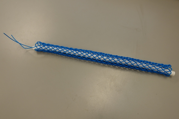
Weave the braid following these rules: 1. The wire will go clockwise around the template (looking at the top of the template) on a braid. 2. The lines drawn on the template will aid the weaving process. Start the weaving process from the bottom of the template, at points where a line is drawn on the template, the wire will always be on top. When going back down, from top to bottom, where a line is drawn, the wire will always be underneath. In this way, the wire travelling in one direction will always be over at the first point, under at the next, over again at the following one and so on. 3. When you reach one end of the template (i.e. the top), the wire should continue clockwise towards the opposite direction (i.e. downwards), following the next available groove/'valley' on the template. Occasionally, the next groove/'valley' is unavailable; in that case, make a tiny loop (circled on the right of the second image) and continue weaving in the same circular direction. |
|
|
Once the weaving is done, clip the wires with several inches to spare. Then detach the braid ends from the template to remove the braid. |
Assembling the Smart Braid into an Actuator
Once you've woven the Smart Braid, it's time to attach it over the tube and assemble it into an actuator. For this step, you'll need a 30 cm length tubing, gasket maker and super-glue. Also two of each of the following: barbed couplers, tooth-lock washers and hose clamps.
Materials

- Smart Braid
- 30 cm silicone tube (1/4" ID)
- Two barbed tube couplers (1/4")
- Two hose clamps (1/4")
- Two external tooth lock washers (from McMaster)
- Silicone sealant
- Super glue
Assembly
 |
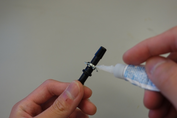
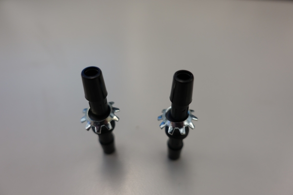
Apply super glue to the concave surface of the washers and affix to the barbed tube couplers, teeth facing inward. |
 |
Allow the tube couplers to dry upright, with the washers' teeth facing down. Ensure that the washer is as flat as possible (i.e. normal to the coupler axis). Leave the coupler to dry for about a day. |
 |
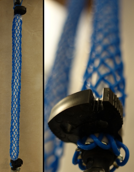
Slip the silicone tube through the Smart Braid; its length should fit the braid just right. Fit the tube connectors into the silicone tube with the washer teeth facing outwards, and hook the loops at the end of the Smart Braid to the washer teeth. |
 |
Attach the hose clamps afterwards on both ends of the Smart Braid. Optional: wrap some scotch tape around the end of the actuator before attaching the hose clamps to ease the clamping process. |
After the smart braid is assembled, the inductance will need to be measured with a device. Two possible methods have been outlined in the modeling section.


