Design
Object Retrieval Scenario
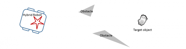
As a goal for demonstrating a working system, the team devised an example object retrieval scenario, described below. This scenario served to solidify the required functionality for the robot.
|
1) The hybrid robot (combination of rigid-bodied and soft robots) moves toward the target object (minion), which cannot be reached by the rigid-bodied robot due to obstacles. |
 |
|
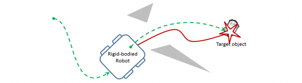
2) The rigid-bodied robot stops, then deploys the soft robot (red). The soft robot moves toward the object and grasps it once there. |
 |
|
3) The soft robot, grasping the minion, returns to the rigid robot, and both are retrieved. |
 |
Design Criteria - Rigid-Body Robot
The design for the rigid platform is largely constrained by our ambitious task of demonstrating autonomous object retrieval. We require the robot to have size large enough to house and power all elements of a soft robot, specifically, the air manifold, valves, Arduino controller, and the soft robot itself. We also necessitate a vision system capable of tracking the location of the soft robot in 3D space. Next, we require the computational resources necessary to implement the object retrieval task in real time and integrate the functionality of both types of robots on a single host computer. One of the attractive features of soft robots is their cost effectiveness and portability. We lastly aim to extend these benefits to the hybrid robot, by keeping the hardware at a reasonable cost in a package that is relatively small and lightweight.
Design Criteria - Soft Robot
The soft robot is required to move anywhere in a planar environment bounded only by its support tether in a potentially cluttered space. Specifically, the robot is required to move in a circular domain with radius of at least 1 meter, and was required to climb over small objects and grasp a small item (both ball shapes of at least 1-inch diameter).
The Rigid-Bodied Robot
Comparison of Rigid-Bodied Candidate Robots
We require an autonomous mobile robot platform that provides plenty of room to place the pressurized system to control the soft robot. The table below briefly compares the hardware specifications of both the KUKA youBot and a customized iRobot Create (similar to the rigid platform in Stokes, et. al., 2014). Based on this comparison, the youBot holds more potential than the Create with respect to many of the stated design criteria: ease of software development, sensor capability, mobility, ability to manipulate, and extensibility. We therefore choose the youBot at the sacrifice of two categories - size and cost - which is justified since the size and cost is still competitive with many customizable, sensor-rich and commercially-available autonomous robots available on today's market.
| Robot Type | iRobot Create with BeagleBoard onboard computer | KUKA youBot with single arm |
| On-board Computer | beagleboard-xM, AM37x 1GHz ARM processor, 512 MB RAM | Mini-ITX, Intel Atom D510 Dual Core 1.66 GHz, 2GB RAM, 32 GB SSD |
| Operating System | Linux | Linux |
| ROS Support | Limited | Good |
| Base Type | Two-wheel differential drive (nonholonomic drive) | Four omnidirectional wheels (holonomic drive) |
| Manipulator | None | 5 DOF arm with 2-finger gripper |
| Sensor Capability | Webcam, sonar | Extensible - RGB+D camera, LIDAR |
| Dimensions | 33.8 cm diameter x 8.8 cm height | 58 cm x 38 cm x 14 cm |
| Cost | ~$200 | ~$20K |
The KUKA youBot (pictured below) consists of an omnidirectional platform, with a five degree-of-freedom manipulator with a two-finger gripper. The arm is an attractive feature, because it allows a way for the soft robot to be deployed from a convenient location atop the robot, and also allows the soft robot to be retrieved once it grasps the object of interest. Our youBot is also equipped with an ASUS Xtion Pro RGB+D (color image + depth image) camera similar to the Microsoft Kinect. The youBot is provided with open interfaces and includes ROS and comes pre-configured with controller drivers. The wheels are omnidirectional, allowing the robot to move freely in any direction with any orientation.

image source: http://www.kuka-labs.com/
The Soft Robot
|
The soft robot design cycle followed a "spiral development" process, with a design that evolved according to the needs of the system as a whole and limitations uncovered during testing. As such, our design followed a natural progression, where the existing functions would be assessed and new features would be included at each increment in the spiral. The picture to the right exemplifies the development process for our project. Starfish Robot DesignsVarious configurations of channels and legs of the soft robot allowed for different choices in actuation sequences. Testing began with two versions of a five-legged design. The design pictured below consists of five independently-actuated air channels and a small rib size. This design was compared against with a similar five-legged design with thicker rib size, but testing revealed that this design was more fragile and more prone to rupture. |
Top to bottom: progression of the soft robot designs tested, including variations developed for our application. |

For most preliminary five-legged designs, a sequence of inflating back legs, inflating front legs, deflating back legs, and deflating front legs resulted in an undulating gait when deflate times were allowed to be longer than inflate times. By inflating sharply and deflating slowly, the contact points between the legs and the ground moved forward quickly but did not move back, moving the center of mass of the robot in a controllable direction. However, the resulting movement was slow, since the center of the robot was always in contact with the ground. This constraint also meant that the five-legged design could not raise itself above an object to grasp.

Additionally, keeping one leg permanently deflated (acting as a pivot) and inflating the remaining legs in sequence resulted in a turning gait. However, the angle change was minimal, once again due to most of the soft robot remaining in contact with the ground.
Quadruped Robot Designs
To mitigate the aforementioned issues with the five-legged design, four-legged designs were adopted. Each leg contained two air channels, allowing a paddling motion for each leg to be developed. This was achieved by inflating the back channel (pushing the leg down and forward), inflating the front channel (pushing the leg further down and back), deflating the back channel (pulling the leg up and back), and deflating the front channel (pulling the leg up and forward). By actuating diametrically opposed legs synchronously, interleaving actuation sequences of opposing pairs of legs, and, once again, allowing deflate times to be longer than inflate times, the soft robot was able to move along one of its axes of symmetry.
The quadruped is pictured below, along with a diagram showing the internal structure. For our project, the conceptual design and dimensions in the diagram were used in our design. In our design, we require a place for the manipulator to grasp the soft robot. Our initial design features a silicone tab attached to the top of the soft robot. This tab is visible in the picture below. Other differences are explained in the Fabrication section.
 |
Diagram of the quadruped design, Stokes, et. al. 2014. |

Designing for Manipulation and Vision-Based Tracking
Because the silicone tab did not stand upright, a 3-D printed tab was designed instead and mounted to the soft robot, as shown below. The tab was colored yellow and the soft robot was given the same color in order to produce a ensure that the youBot's perception system can reliably track the soft robot when placed at a reasonable distance away from the youBot and and be robust to changes in the soft robot's orientation.

After testing the soft robot, it was concluded that the yellow tab alone was sufficient to track the soft robot's location using the vision system. Emphasis was placed on coloring the robot such that its orientation with respect to the youBot in any of the four cardinal direction is easily distinguishable. That way, the youBot can provide appropriate commands to move the quadruped toward its goal without resorting to a "guess-and-check" type of control strategy.
The design concept operates on the same principle as a binary color encoder with resolution down to the nearest quadrant. We describe its operation through an example. Assuming the two black legs represent the front of the robot, if a black leg is visible to the left and a white leg to the right in the camera image, then we know the front of the robot is facing left in the camera image. Now, assuming that we want the soft robot to move left in the camera image, it is required to actuate a gait to move the robot forward. By color coding the robot in this way, the control system is robust to variations in how the soft robot is oriented when placed on the ground.
To prevent leaks and having the tubes from being damaged or removed when the youBot manipulator picked up the soft robot, the piping was glued into the soft robot. Because this interfered with the plastic tab, yellow tape was instead used to secure the tubing. The tape served three purposes: to keep the tubing from separating, to act as a handle for the manipulator to pick up the robot, and to act as a color "blob" that could be seen by the youBot vision system.
The tether length was an important factor in the design; the considerations were range of motion, potential for entanglement with the youBot manipulator and wheels, effect of the tether's drag on quadruped mobility, and dynamic range of the vision sensor used for tracking the soft robot.
The published range of the depth readings for the ASUS Xtion Pro camera is between 80 cm and 350 cm. Because the manifold was situated toward the rear of the youBot, 50 cm was added to the required forward travel of the soft robot beyond the front of the youBot. To satisfy the camera constraints, a tether length between 120 cm and 400 cm was required. We ultimately chose 150 cm as the tether length, as this satisfied having reasonable mobility within the field of view of the sensor (between zero and 100 cm from the front of the robot), while keeping the effect of drag small and risk of entanglement low.
Task-Level Control of Soft- and Rigid-Body Robot Behaviors
Camera Integration
The ASUS Xtion Pro camera was used for tracking the soft robot and the target object to be retrieved. It provides both RGB and depth data. As pictured below, the camera was mounted on the front of the youBot. The camera could also be mounted on the wrist of the arm, but since the object and soft robot will always remain at ground level, the front mount was chosen.

The ROS OpenNI package was used to launch the camera driver and access camera data. The ROS package Cmvision was also used to aid with blob color detection in order to locate the red object and the yellow tag on the soft robot in the camera frame. In order to detect the blobs, the following procedure was used.
1. Launch the OpenNI camera driver: roslaunch openni_launch openni.launch
2. Run the Cmvision blob detector color tool: rosrun cmvision colorgui image:=<image topic>
3. Click on the blob you would like to detect until the RBG and YUV color values are given by the GUI.
4. Edit the colors.txt file to include the YUV color of the blob to detect.
5. Launch the Cmvision blob detector: roslaunch cmvision cmvision.launch. A GUI that looks like the image below should appear, outlining the blobs detected with a box. The image below depicts the red object being detected.

More information on the OpenNI and Cmvision packages can be found by viewing their ROS wiki pages:
Vision-Based Soft Robot Navigation
Once the youBot deployed the soft robot, the youBot communicated with the Arduino via a serial communication. A state machine on the Arduino processed incoming commands and executed corresponding actuation sequences for the soft robot. The camera data was used to generate a reference signal based on the position of the target and an error signal based on the position of the soft robot, which were then used to decide which commands to send to the soft robot next. The simple control logic is given below. Here "position" and "reference" are, respectively, the 2D positions of the soft robot and target object in camera coordinates, and "threshold" is a threshold of 20 pixels in the image.
if position < reference - threshold:
execute "move right" gait for 1 sec
else if position > reference - threshold:
execute "move left" gait for 1 sec
else:
execute "move forward" gait for 1 sec
The code for controlling each of the gaits is discussed in the testing section of our wiki.
Task-Level State Machine
To execute the object retrieval task and coordinate the motion of the youBot and soft robot, a state machine was designed. This was done using the ROS Smach (state machine) package. A diagram summarizing the states as well as a brief description of all states is provided below.

Description of states:
Search: The Search state is the initial state of the machine. In this state, the youBot turns clockwise, looking for the object. Once the "/blobs" topic from the Cmvision package returns that it has found a red blob, the youBot rotates to face the blob. It then accesses the depth data of the blob and the state calculates the blob's coordinates in the global coordinate system. Once this has occurred, the Search state exits on "found" and transfers the coordinates of the blob to the next state.
Drive: The transition "found" goes to the Drive state. In this state, the youBot uses the coordinates of the blob from the Search state and drives to those coordinates. The youBot actually drives to 20 cm away from the coordinates in order to give the arm and soft robot room to reach the object. Once the youBot is at the proper coordinates, the state machine returns "here", which brings it to the next state.
Dropoff: The next state is Dropoff. In this state, the arm picks up the soft robot from the back of the youBot and drops it off slightly to the right in from of the youBot. Once the soft robot is dropped off, the state returns "deployed" and transitions to the next state.
Wait: The next state is Wait. This is where the youBot stays still, but sends commands to the Arduino for the soft robot. Additionally, the blob detection is run in this state, and the youBot tells the soft robot to move right or left depending on its relative position to the blob (comparing the yellow and red blobs). Once the soft robot gets to the object, the state returns "reached".
Return: "Reached" brings the state machine to to the final state: Return. This brings the arm back to its original position and once the arm is there outputs "done". "Done" brings the state machine to its exit state, also named "Done". This is the end of the state machine and the task is complete.