Fabrication
This section provides details on the required steps for fabricating the prototype robot. This includes a description of the pneuNet fabrication process, the controller board for the soft robot, and the pneumatic system.
The required bill-of-materials for assembling each of the subsystems is as follows:
| DESCRIPTION | QUANTITY | UNIT COST | TOTAL COST | PART NUMBER | SUPPLIER |
| Flow control | |||||
| Manifold, High Flow | 1 | $ 32.96 | $ 32.96 | 4750K29 | McMaster |
| Valve 3-Way, NC, 24DC, High Flow | 8 | $ 37.50 | $ 300.00 | Parker | |
| Electronics | |||||
| Arduino Uno | 1 | $ 21.00 | $ 21.00 | AA-011003 | yourduino |
| Toggle switch | 3 | $ 1.75 | $ 5.25 | B001TJ0ZAG | PartsExpress |
| Breadboard (with jumper wires) | 2 | $ 13.50 | $ 27.00 | B004RXKWDQ | microtivity |
| Zener Diodes | 8 | $ 0.25 | $ 2.00 | 1N4733A | sparkfun |
| N-Channel MOSFET 60V 30A | 8 | $ 0.95 | $ 7.60 | FQP30N06L | sparkfun |
| Screw Terminals 3.5mm Pitch (2-Pin) | 11 | $ 0.95 | $ 10.45 | 284391-2 | sparkfun |
| Miscellaneous | |||||
| PVC Tubing 1/8", (per foot) | 50 | $ 0.15 | $ 7.50 | 5233K51 | McMaster |
| PVC Tubing 1/4", (per foot) | 25 | $ 0.13 | $ 3.25 | 5233K52 | McMaster |
| Tube Fitting 1/8"to 1/16" | 1 | $ 8.21 | $ 8.21 | 2974K291 | McMaster |
PneuNet Actuators
This section outlines the steps taken in fabricating the PneuNet actuators that make up the legs of the "minion" bot used in our project. The following visualizations are approximate, as the molds used for the different kinds of robots had slightly varying PneuNet channels, but they show the general structure and fabrication methods. As with most PneuNet actuators, they are constructed in two parts: an upper portion made of an elastomer that is extensible, and a bottom portion also made of an elastomer, but with an inextensible sheet inlaid in the elastomer to prevent it from straining. These layers are then bonded together to form a sealed channel. One characteristic feature of our particular design of PneuNet actuators is that the walls in between the separate chambers are mostly connected to the bottom layer except for a relatively small opening for air to get into the next chamber. This allows for a greater translation of forces through the two layers, resulting in a more pronounced bending motion. For our particular minion bot, the elastomer of choice was EcoFlex for its durability, ease of use, and relative accessibility (starting with EcoFlex-0030 and moving on to EcoFlex-0050 throughout the project for increased shear strength). All versions of EcoFlex used are available here from Smooth-On. The inextensible mesh used was a simple nylon sheet. The method described in this section for fabricating the PneuNet actuators used in this project is similar to that described in this separate project featured on the Soft Robotics Toolkit website.
Steps to Fabrication of the PneuNet Bending Actuators
 |
Step 1Mix both parts of the EcoFlex in a 1:1 ratio. Let the mixture sit in a vacuum chamber for a short while until it seems most of the air bubbles have vacated the mixture (so as the bubbles do not get into the final robot creating holes or inconsistencies in the air channels). Pour the uncured EcoFlex (purple) into the mold (blue). At the same time, pour EcoFlex in a thin layer over a nylon sheet (white solid line) placed on a Plexiglas surface to act later as the bottom layer of the channel. |
 |
Step 2Both portions of EcoFlex may be placed in an oven to accelerate the curing process. Once the EcoFlex has cured (gray), the top layer of the channel should be removed from the mold. |
 |
Step 3Pour another thin layer of prepared EcoFlex on top of the layer that was already cured onto the Plexiglas. It is important to note that the base layer should be cool to the touch before pouring (especially if an oven was used to speed up the curing process) or else the EcoFlex may begin curing too rapidly before reaching the next step (in our case, this mistake occasionally caused undesirable peaks and valleys in this second thin layer of silicone, occasionally blocking some of the air passages). |
 |
Step 4Affix the top layer to the bottom layer when the thin layer of EcoFlex applied in Step 3 is still uncured and let sit in standard conditions until this layer cures. It is recommended that you DO NOT use an oven to expedite the curing process at this step because the increase in temperature can cause the expansion of gases in the channels themselves leading to a greater chance of having holes an inconsistencies in the final product. |
 |
Step 5Remove the entire robot from the flat sheet of Plexiglas. Use an X-Acto knife, scissors, or other cutting tool of your choice to remove enough excess material from the sides of the robot to make it more functional yet not so much as to jeopardize the seal between the top and bottom layers at the outside walls. |
 |
Step 6Now that the robot is fully cured, released from its molds and trimmed, narrow, inextensible tubing can be inserted into the desired area of the channel to act as the point of entry for the air from the solenoid system. Although this can be achieved by cutting the end of the tube at a 45 degree angle and forcing this end through the silicone, it was found that there could occasionally be leaking in these areas at higher pressures. If desired, a few drops of krazy glue in the entry area was found to help mitigate this issue. |
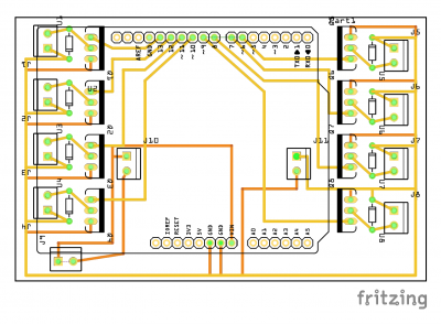
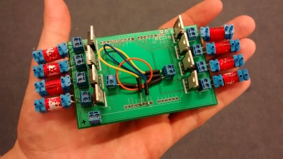
Printed Circuit Board
A prototype for the electrical system was built on a breadboard for the five-legged designs, using NPN transistors to control the valves and diodes to handle current discharge from the valves. When scaling the design to an eight valve system, the circuit became far more fragile and began to fail more often. A printed circuit board (PCB) was designed to mitigate this problem. It attached to the Arduino as a shield, and the eight valves connected to screw terminals along the sides of the board. The Arduino and circuit were powered via the Arduino serial interface, as this was already being used to communicate with the youBot.
Assembly of the Hybrid Robot
Pneumatic System
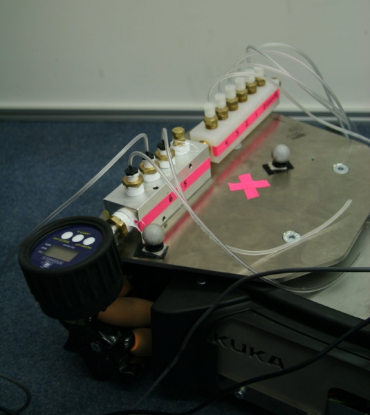
For the initial testing of the soft robots, a compressed air tank system was used along with a pressure regulator to limit the internal pressure of an existing manifold. A series of three-way solenoid valves connected to the ports of the manifold would open and pressurize the channels, or close and restore the channels to atmospheric pressure.
The main problem encountered with this system was leakage at the channel interface. Inserting the tubes into the channels without adhesive was sufficient for early testing of the starfish and quadruped robots. Over time, this caused the interfaces to grow wider, letting air out of the robot and decreasing the maximum attainable curvature of the corresponding leg, and uniformity of pressurization. To solve this problem, we attempted to bind the tubes to the legs using first silicone, then ethyl cyanoacrylate (Krazy Glue). Only the cyanoacrylate closed the interfaces successfully. A pressure sensor (with digital readout) was added to assist with open-loop testing of the soft robots.
For final testing of the system and demonstration, the manifold and valves were mounted onto the youBot base plate, as pictured below.