FeTCh Mark 1 Manipulator
Introduction
The objective of this project is the design and implementation of a soft manipulator robot based on hybrid actuation capable of interacting with delicate objects and with the ability to team up with humans with safety due to non-hazardous contacts. Due to the actuation system used in the design associated with a new control approach, simultaneous stiffness and position control is achieved in the manipulator.
Overview
In the next section, you can find information related to the motivation and inspiration behind this project along with some examples of previous work related to continuum manipulators.
The fabrication of soft robots, while simple, is time-consuming. Therefore, in order to optimize our designs we opted to test the behavior of the components of the prototype previous to their fabrication. In the design section details the process of concept design and simulation of the prototype components as well as the files required to accomplish the fabrication of the prototype.
The fabrication section presents the detailed steps of the implementation of the prototype, and finally, in the testing section, we talk about the modeling approach we use to describe the behavior of the manipulator as well as the simulation of the complete prototype. A demo of the manipulator is presented in this section as well.
Background
Motivation and inspiration
Rigid manipulator robots have, as of this moment, a clear advantage over soft manipulators concerning the force generation and because of their stiff nature, the problem of position control is easily addressed. Nevertheless, the compliant structure of soft manipulators makes them suitable for tasks such as handling delicate objects in which the forces required are really minimal and where high inertial forces can damage the object being manipulated. Also, the contact energy on a soft manipulator is mostly transformed into deformation of the soft structure, which allows robots and humans to work safely and efficiently as a team. Still, because of the compliance of soft manipulators, some problems concerning vibrations and deviation from the desired position arise. Therefore, the implementation of some level of stiffness control is required in soft manipulators in order to operate efficiently.
|
|
 |

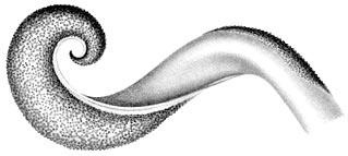
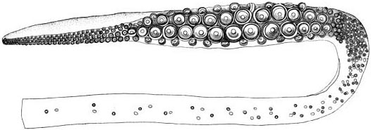
If we take a look at nature, we can find some animals that achieve this rigidification of some of their limbs in an easy manner. The octopus tentacle and even the human tongue use antagonistic actuation to control their stiffness. What this means is that a muscle (or actuator in our case) is used to move the limb to a certain position, while a second muscle is used to counter-actuate this first one in order to produce the effect of rigidification or change in the apparent stiffness of the limb.
With the concept of antagonistic actuation in mind, we can think of a suitable actuation scheme that can emulate such actions. In the field of soft continuum robots, two main actuation classes can be identified: 1) Intrinsic actuation: The construction of intrinsic mechanisms combine the actuation and the supporting structure into a single unit. This actuation is mostly fluid operated and the operation relies on the elastic deformation of the actuator chambers. Internal pressures are controlled to generate extension forces and the structure deforms according to constraints provided by the end form [Robinson and Davies et al.]. 2) Extrinsic actuation: Extrinsic mechanisms use remote actuation, and transfer motion to the structure via groups of tendons or cables to achieve the bending of the backbone [Walker et al.]. For this project, a hybrid actuation scheme is implemented in our prototype, in which pneumatic and tendon actuators antagonize each other to accomplish the motion of the manipulator while allowing a certain level of stiffness control.
 |
 |
In the literature, we can find some examples of continuum manipulators that implement hybrid actuation. In McMahan et al., researchers from Clemson University, USA, present the design and implementation of a continuum robot based on hybrid actuation. In this example, the central cavity that functions as a backbone for the robot is pressurized to provide structural support and cable-tendons routed through cable guides along the backbone apply forces to it to make it bend. This prototype uses the pressurized central chamber to generate extension as well. The limitation of this design is the lack of strength due to high cable friction that cannot be overcome by low pressures in the central chamber.
Neppalli and Jones addressed the flaws of the previous design in Neppalli et al. by replacing the central hose by a rubber tube. The resulting design has more flexibility and strength capabilities. A noticeable limitation of the design remains in the cable friction that can cause binding and undesirable motions of the backbone.
It is interesting to notice that while this design use hybrid actuation, the pneumatic actuators are used to provide structural support or extension, and the cables are used to achieve bending.
Images
"Giant squid tentacle club". Licensed under Public Domain via Wikimedia Commons - http://commons.wikimedia.org/wiki/File:Giant_squid_tentacle_club.jpg#/media/File:Giant_squid_tentacle_club.jpg
"Austrorossia mastigophora2". Licensed under Public Domain via Wikimedia Commons - http://commons.wikimedia.org/wiki/File:Austrorossia_mastigophora2.jpg#/m...
"Gray1019" by Henry Vandyke Carter - Henry Gray (1918) Anatomy of the Human Body (See "Book" section below)Bartleby.com: Gray's Anatomy, Plate 1019. Licensed under Public Domain via Wikimedia Commons - http://commons.wikimedia.org/wiki/File:Gray1019.png#/media/File:Gray1019.png
"Lgive lashon" by צביה. Licensed under CC BY-SA 3.0 via Wikimedia Commons - http://commons.wikimedia.org/wiki/File:Lgive_lashon.JPG#/media/File:Lgiv...
Design
This project consists of the development of a soft manipulator based on antagonistic actuation capable of bending and extension with a certain degree of stiffness control. It makes use of a hybrid actuation system composed of pneumatic and tendon-based actuators.

This section presents the design of each part that compose the robot, while providing the operation principles that led to that particular design.
Designing the pneumatic actuators
The first step in this project was to design the pneumatic actuators. The idea was to design actuators that extend when compressed air is injected inside them, contrary to the operation of the McKibben actuators that contract when pressurized. Actuators made of silicone that do not require a braided sleeve in order to constrain the deformation were desired. This choice led to a design of our actuators with a “folded” shape, similar to an accordion.
 |
When pressure is applied inside the cavity of the actuator, the walls of the actuator unfold and produce an elongation of the actuator.

Since the time required to build the actuators is considerable, we first simulated it to confirm the expected behavior. This simulation is based on the Finite Element model of the actuator and was performed using the SOFA Framework (https://www.sofa-framework.org). Once the simulation provides satisfying results, we proceed with the fabrication of the actuators.
|
|
Having the simulation of the deformable parts of the prototype is of great help because it gives a good idea how these parts will behave before their fabrication. By analyzing the simulation, we know if the design needs modifications without having to test the real part in the lab. Also, a suitable way to pilot this model is by using using this model in open loop with the real prototype.
Design of a Stewart platform like section
To achieve bending in our robot, three actuators are arranged in parallel configuration as one section of the manipulator. A rigid platform at the end of the array holds the actuators in place. By applying different pressure values to each actuator, we can displace or orientate this platform.

When differential pressures are applied to the actuators of one section, the top platform is oriented in different ways. If equal pressure is applied to all the actuators, the manipulator elongates longitudinally.
The design of the platform is very simple. It is composed of 3 sockets that receive the actuators and hold them in place. A hole at the bottom of each socket provides the necessary space to connect a plastic tube, from the air supply to the actuator, and a central hole in the platform allows us to pass the tube that will supply the air to the actuators of the second section. Smaller holes located between the sockets serve as cable guides for the tendons.

The manipulator is composed by serially connecting two sections. The pose of the manipulator is controlled by six pneumatic inputs, while the stiffness is controlled by six antagonist cable actuators. These cables run along the same direction of the pneumatic actuators and pass through holes in the rigid platform. The cables are positioned carefully to avoid contact with the pneumatic actuators and minimize the friction during bending.

Once the behavior of one section of the manipulator was proven, another simulation was made to include both sections to better picture the behavior of the whole manipulator.
Additional Parts
|
Each tendon is attached to a servomotor. More specifically, to a pulley that is connected to the shaft of each servomotor. This is why six supports of servomotors and six pulleys were designed and built. The servomotors used are rated to a 0° to 180° span, although in practice, each one turns in the range of 35° and 158°. That means we need to use a pulley that could give us enough force to pull the different parts of the manipulator, while keeping an appropriate stroke according to the simulation's results. Each section of the manipulator was measured to an elongation of 1.5cm, twice this distance must be considered for the second section. Therefore, a pulley of 3.6cm of diameter was designed , giving a safe 3.8 cm of stroke.
To keep the servomotors in place, a support visible on the picture below had to be designed. This design allows the six actuators to work in a reduced volume, while keeping the cables free from tangling up and leaving at the same time enough room for the pneumatics tubing.
|


Fabrication
This section presents the steps required for the fabrication of the robot, as well as the list of materials and tools needed. The CAD files of each part of the prototype can be found at the end of each sub-section.
List of Tools and Materials
 |
Dragon Skin 10A silicone rubber The pneumatic actuators and the end-effector are made of Dragon Skin 10A silicone rubber by Smooth-On, which has a good compromise between elasticity and tear strength. |
 |
OpenBeam 12 beams of 30cm long are required to build the frame of the base of the manipulator. In order to join the beams together, some A-brackets and bolts are needed as well. |
 |
Wooden plank A wooden plank of 30cm x 30cm was used on top of the beam frame as a fixation platform for the manipulator and the servos. |
 |
Polyethylene tube Polyethylene tube of Ø4mm is used to connect the pneumatic actuators to the valves. |
 |
Fishing line Fishing line of Ø.35mm functions as our cable-tendons. It is very resistant and thin. |
 |
Bolts and nuts We used 4 bolts of Ø4mm to fix the manipulator to the wooden plank. The required length of these bolts depend on the thickness of the wooden plank selected., A total of 22 bolts of Ø2.5mm and 10mm long and 3 bolts of Ø2.5mm and 30mm long are used in the assembly of the manipulator. |
 |
Scissors We used scissors to remove silicone excess from the actuators. |
 |
Cardboard cutter Same as the scissors, the cutter is use to clean and detail silicone and plastic parts. |
 |
Dremel tool The Dremel tool is used to detail the plastic parts in case the 3D printer left some plastic residue. Since we are working with silicone rubber, it is important to check for plastic edges that can puncture the silicone or prevent any other piece to fit in place. |
 |
Electric drill Same as above, the drill is used to finish the holes in the plastic pieces and to make some holes in the wooden plank so that the manipulator and servos can be attached in place. |
 |
Ultimaker 3D printer A Ultimaker 3D printer was used in the fabrication of all the rigid parts of the manipulator. |
 |
ProJet 460 plus 3D printer We had the fortune of having access to a ProJet plus 3D printer. With it, we were able to print plaster molds for the silicone parts, since the plastic molds are quite difficult to handle. |
Fabrication: A step-by-step guide (part 1)
This section presents all the steps needed to build the prototype. Some comments regarding possible problems or improvements in the process were added. These steps are:
- Fabrication of pneumatic actuators
- Printing the rigid platforms
- Building one section of the robot
- Building the base frame
- Final assembly
Fabrication of the pneumatic actuators
The soft backbone of the manipulator is composed of pneumatic actuators. These actuators are made of silicone rubber, and when inflated, they elongate longitudinally.

The first step to casting the actuators is printing the mold. The molds were designed to hold half of the actuator. In this case, the molds were made out of plaster using the ProJet 460 Plus printer, but molds made of a conventional plastic for 3D printing should do just fine as long as its surface is conveniently lubricated. This choice was motivated by the smoother surfaces produced by the plaster post-treatment with cyanoacrylate, making the unmolding much easier.


Once the molds are printed, it is time to cast the actuators. For this, Dragon Skin 10A silicone rubber is used. This silicone comes in a two-compound presentation which is really easy to prepare: just mix part A and part B in a 1:1 ratio, according to the amount of silicone you will need. If you have access to a vacuum chamber, you can put the silicone mixture in it to take out all the bubbles that can appear when the two parts are mixed. This allows to have a really homogeneous silicone piece.

Once the silicone mixture is ready, simply pour some mixture into the molds until the mold cavity is completely full. Then, put the cap on the mold while being careful with the alignment between the mold and the cap. For this initial test, we casted just two halves to have one actuator.


The two halves of the actuator should cure after about 3 to 4 hours. To join them, put some silicone on the edge of the wall of the piece and use the molds to align each half. Once the silicone is cured, you can take out the actuator from the molds. Use a hobby knife to remove any excess of silicone from the actuator.


The rigid platforms
There are three different types of rigid platforms involved in the assembly of the manipulator. These platforms have sockets that allow us to keep the actuators in place. The sockets have an entry hole for the polyethylene tubes. All of these platforms use a second piece on top that functions as a cap, this cap makes it easier to put the actuators on the sockets.
The first platform is the base, which is attached to the wooden plank and receive the first three pneumatic actuators. To attach this platform to the plank, Ø4mm bolts were used, long enough so that nuts can be fastened to the other side of the plank. Another three Ø2.5mm 10mm long bolts are used in the center part of the platform to fix the cap in place. Six more holes between the sockets are used to guide the cables along the manipulator.

The cap is placed on top of the platform and is fixed to it using bolts.

The middle platform is based on the same design. This platform connects the first section to the second and is composed of four pieces because it has six sockets in total and 2 caps. There are no 4mm holes and the bolts used to assembly these part are longer (30mm). A slight modification is done to the upper socket part in order to allow the connection of the tubes that supply pressure to the second section. Both cap pieces used in this platform are exactly the same.


The top platform receives the second set of pneumatic actuators and completes the second section. The design is the same as for the middle platforms.


Fabrication: A step-by-step guide (part 2)
Building one section of the robot
Once three actuators are made and a couple of platforms are printed, the assembly of one section of the manipulator is an easy task. Just put the actuators in the sockets of a sandwich of platforms, connect the tubes for the pressure supply, and close the caps.


Building the base frame
In order to have a suitable fixation base for the manipulator, a frame made of beams was built. This frame is composed by 12 beams of 30cm of length with some A-brackets to keep it together. OpenBeams were chosen because of the readiness of the materials and because more brackets can be 3D printed needed.

Cover the frame with the wooden plank. With the use of the electric drill, cut suitable holes in the shape of the base rigid platform of the manipulator, so that there is easy access to the connection holes of the sockets and also the cable guides.

Finally, attach the plank to the frame using bolts from the bottom up. The servos will be placed on top of the cover, while the manipulator will be attached to the plank at the bottom side. The manipulator will be operating hanging from the cover of the base.

Fabrication: A step-by-step guide (part 3)
Final assembly
Once all the parts of the manipulator are fabricated, we can start the final assembly of the robot. The first step is to attach the base platform to the bottom of the plank in the base frame. As explained before, long bolts of Ø4mm and nuts are used to fix the platform.


The next step is to connect the second section to the first one. 30mm long Ø2.5mm bolts are used to attach the two parts of the middle rigid platform; this was done with the objective of having a small gap between the two parts of the middle platform, so that the tubes that supply the air to the second set of pneumatic actuators could have some room to bend.


With both sections in place, we can start putting the cables through their dedicated holes. There are six cables in total, three of them go from the base to the middle platform, while the other three go from the base to the top platform. The cables are actuated by servos placed on top of the base cover. Special care is needed while putting the servos in place, to make sure that the pulleys attached to the servos are aligned with the cable holes at the base platform. Nuts were tied up at the end of each cable so that the cables can apply forces to the platforms.


After every part is in its place, the robot looks like this:


Testing
This section provides some explanations about the method we use to control the robot and test its expected behavior. Videos of the different tests made at each part of the fabrication and the piloting of the final robot with a real-time comparison to the simulation of its behavior is also presented.
Model and Control
The robot is composed of 6 pneumatic actuators and 6 cables. The robot is thus highly redundant and composed of hybrid actuation.
To drive the 12 actuators in a coherent manner, a new approach is needed for control. Bosman et al. recently proposed a method dedicated to continuum robots with rigid vertebrae. One important contribution of this work is to demonstrate that the method of control can be extended to hybrid and redundant actuation.
The first step of the method is to build a detailed FEM model of one intervertebra attached to a vertebra. For that, we use SOFA and the plugin dedicated to soft robots. The simulation is able to mix deformable and rigid parts, thanks to a generic definition of the degrees of freedom available on SOFA platform.
The second step is the heart of the method: to avoid computation burden and allow for real-time computation of the robot model, we use a model reduction method based on a domain decomposition approach. The algorithm computes the equivalent non-linear stiffness of the intervertebra.
 |
|
|
| → | ||

The third step consists in building a simplified model of the whole robot and placing the cables. To compute a motion of the cavities with no precise simulation of the intervertebra (because we are using a simplified model), we use a technique often used in computer graphics that is called skinning. From the 6D frame of each intervertebra, the skinning provides a deformable motion of the inner cavity. In SOFA, we can reverse this skinning as done in [Duriez et al 2008] to compute the equivalent force on the frame, due to the pressure applied on cavity walls.

The last step is to launch the inverse control method, presented in [Duriez 2013] and extended in [Bosman et al. 2015]. It consists on inverting the deformable model, thanks to an optimization method and finding the actuator value given the desired position of the effector (here we control all the degrees of freedom (DOF) of the effector, except the twist, so 5DOF). As the robot is highly redundant, we add more criteria in the optimization to get a single solution to the problem: the method minimizes the pressure value (to put as little pressure as possible in the cavities) and it also minimizes the energy of deformation.
Actuator and platform testing
Along with the fabrication phase, the performance of the pneumatic actuators was tested, as well as the real behavior of the "Stewart platform"-like section of the manipulator.
The initial test conducted on a 5cm long actuator showed that a maximum extension of 47% (2.35cm) could be obtained when a pressure of 0.3 bars is applied. If the cavity pressure increases further, the actuator deforms radially. It is then important to operate the actuator inside the pressure range of 0 – 0.3 bars.
|
|
A preliminary test of the real behavior of the pneumatic based Stewart platform was conducted. This test was done without the cable actuators.
|
|
Robot piloting based on FEM simulation
The modeling method and simulation described previously to pilot the robot was used. The inverse model is computed in real-time to obtain the actuation required to orientate and position the manipulator as desired. This position is controlled by moving manually a control point attached to the top platform in the simulation.
The first test was conducted using only cable actuation.
|
|
In the second test, antagonistic (both cable and pneumatics) actuation was implemented in the simulation.