Fabrication
This section presents the steps required for the fabrication of the robot, as well as the list of materials and tools needed. The CAD files of each part of the prototype can be found at the end of each sub-section.
List of Tools and Materials
 |
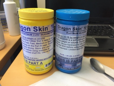
Dragon Skin 10A silicone rubber The pneumatic actuators and the end-effector are made of Dragon Skin 10A silicone rubber by Smooth-On, which has a good compromise between elasticity and tear strength. |
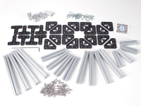 |
OpenBeam 12 beams of 30cm long are required to build the frame of the base of the manipulator. In order to join the beams together, some A-brackets and bolts are needed as well. |
 |
Wooden plank A wooden plank of 30cm x 30cm was used on top of the beam frame as a fixation platform for the manipulator and the servos. |
 |
Polyethylene tube Polyethylene tube of Ø4mm is used to connect the pneumatic actuators to the valves. |
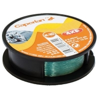 |
Fishing line Fishing line of Ø.35mm functions as our cable-tendons. It is very resistant and thin. |
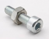 |
Bolts and nuts We used 4 bolts of Ø4mm to fix the manipulator to the wooden plank. The required length of these bolts depend on the thickness of the wooden plank selected., A total of 22 bolts of Ø2.5mm and 10mm long and 3 bolts of Ø2.5mm and 30mm long are used in the assembly of the manipulator. |
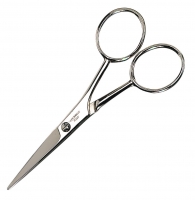 |
Scissors We used scissors to remove silicone excess from the actuators. |
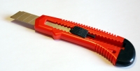 |
Cardboard cutter Same as the scissors, the cutter is use to clean and detail silicone and plastic parts. |
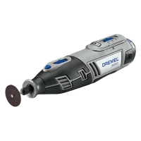 |
Dremel tool The Dremel tool is used to detail the plastic parts in case the 3D printer left some plastic residue. Since we are working with silicone rubber, it is important to check for plastic edges that can puncture the silicone or prevent any other piece to fit in place. |
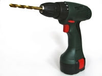 |
Electric drill Same as above, the drill is used to finish the holes in the plastic pieces and to make some holes in the wooden plank so that the manipulator and servos can be attached in place. |
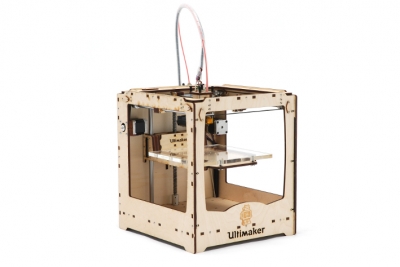 |
Ultimaker 3D printer A Ultimaker 3D printer was used in the fabrication of all the rigid parts of the manipulator. |
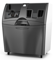 |
ProJet 460 plus 3D printer We had the fortune of having access to a ProJet plus 3D printer. With it, we were able to print plaster molds for the silicone parts, since the plastic molds are quite difficult to handle. |
Fabrication: A step-by-step guide (part 1)
This section presents all the steps needed to build the prototype. Some comments regarding possible problems or improvements in the process were added. These steps are:
- Fabrication of pneumatic actuators
- Printing the rigid platforms
- Building one section of the robot
- Building the base frame
- Final assembly
Fabrication of the pneumatic actuators
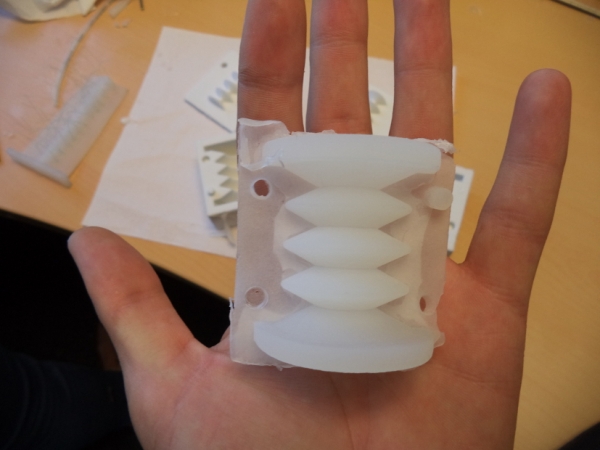
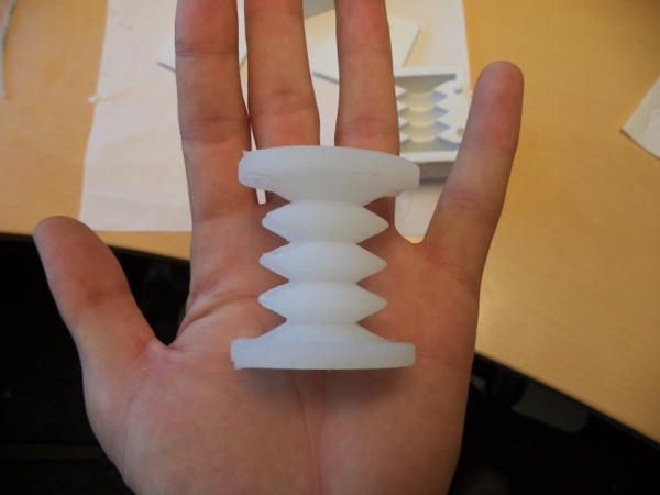
The soft backbone of the manipulator is composed of pneumatic actuators. These actuators are made of silicone rubber, and when inflated, they elongate longitudinally.
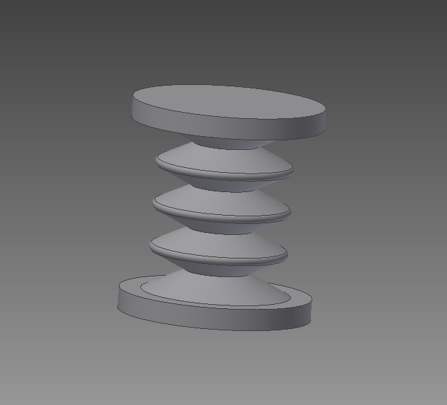
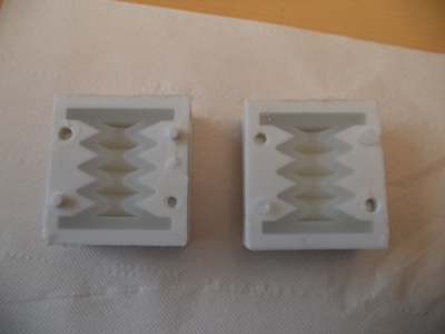
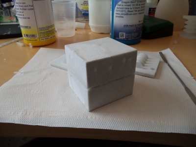
The first step to casting the actuators is printing the mold. The molds were designed to hold half of the actuator. In this case, the molds were made out of plaster using the ProJet 460 Plus printer, but molds made of a conventional plastic for 3D printing should do just fine as long as its surface is conveniently lubricated. This choice was motivated by the smoother surfaces produced by the plaster post-treatment with cyanoacrylate, making the unmolding much easier.
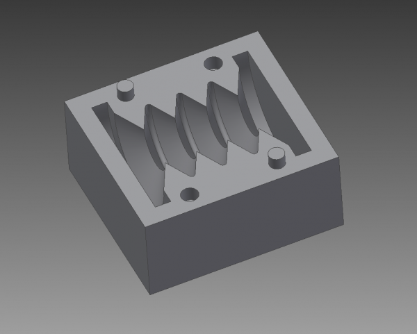
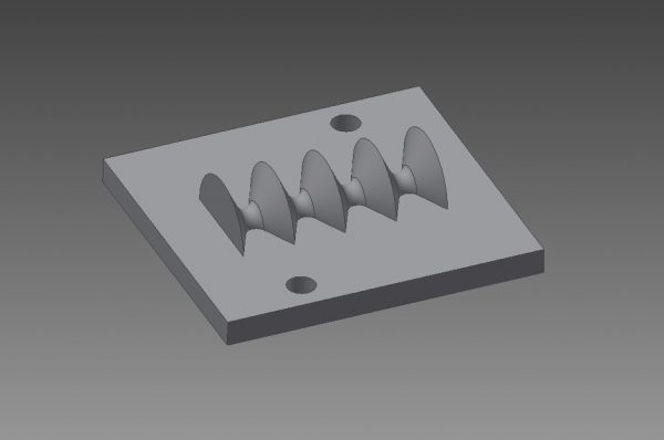
Once the molds are printed, it is time to cast the actuators. For this, Dragon Skin 10A silicone rubber is used. This silicone comes in a two-compound presentation which is really easy to prepare: just mix part A and part B in a 1:1 ratio, according to the amount of silicone you will need. If you have access to a vacuum chamber, you can put the silicone mixture in it to take out all the bubbles that can appear when the two parts are mixed. This allows to have a really homogeneous silicone piece.
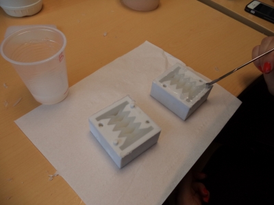
Once the silicone mixture is ready, simply pour some mixture into the molds until the mold cavity is completely full. Then, put the cap on the mold while being careful with the alignment between the mold and the cap. For this initial test, we casted just two halves to have one actuator.
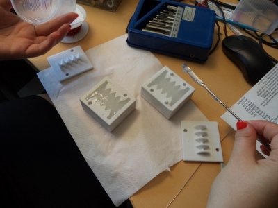
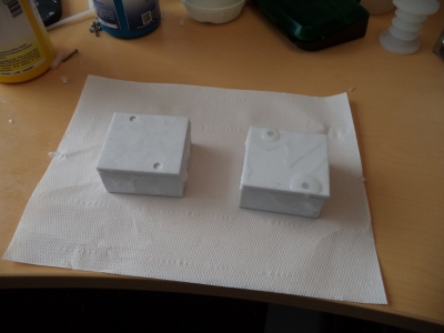
The two halves of the actuator should cure after about 3 to 4 hours. To join them, put some silicone on the edge of the wall of the piece and use the molds to align each half. Once the silicone is cured, you can take out the actuator from the molds. Use a hobby knife to remove any excess of silicone from the actuator.
The rigid platforms
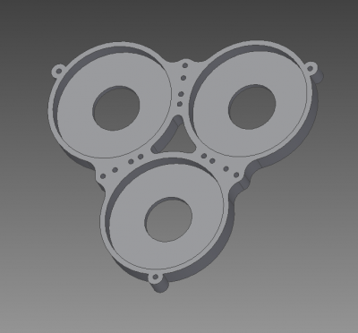
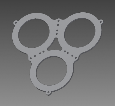
There are three different types of rigid platforms involved in the assembly of the manipulator. These platforms have sockets that allow us to keep the actuators in place. The sockets have an entry hole for the polyethylene tubes. All of these platforms use a second piece on top that functions as a cap, this cap makes it easier to put the actuators on the sockets.
The first platform is the base, which is attached to the wooden plank and receive the first three pneumatic actuators. To attach this platform to the plank, Ø4mm bolts were used, long enough so that nuts can be fastened to the other side of the plank. Another three Ø2.5mm 10mm long bolts are used in the center part of the platform to fix the cap in place. Six more holes between the sockets are used to guide the cables along the manipulator.
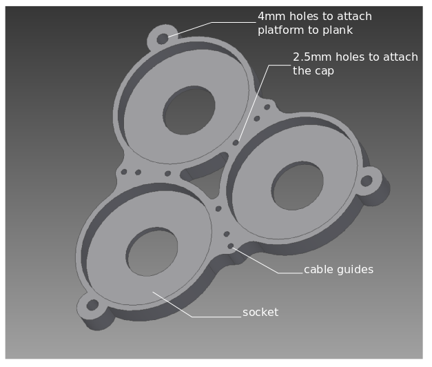
The cap is placed on top of the platform and is fixed to it using bolts.
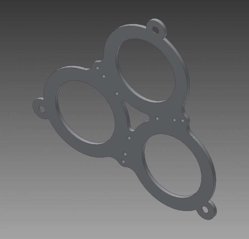
The middle platform is based on the same design. This platform connects the first section to the second and is composed of four pieces because it has six sockets in total and 2 caps. There are no 4mm holes and the bolts used to assembly these part are longer (30mm). A slight modification is done to the upper socket part in order to allow the connection of the tubes that supply pressure to the second section. Both cap pieces used in this platform are exactly the same.
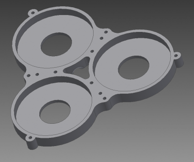
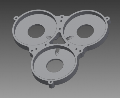
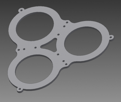
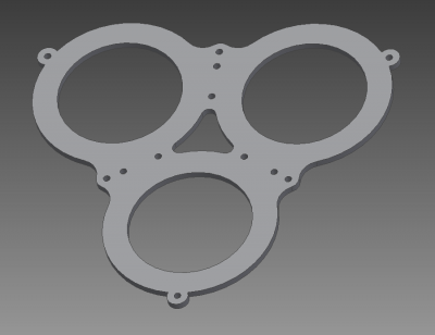
The top platform receives the second set of pneumatic actuators and completes the second section. The design is the same as for the middle platforms.
Fabrication: A step-by-step guide (part 2)
Building one section of the robot
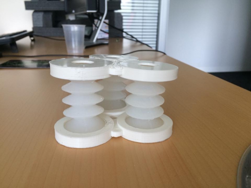
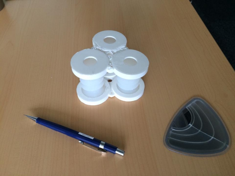
Once three actuators are made and a couple of platforms are printed, the assembly of one section of the manipulator is an easy task. Just put the actuators in the sockets of a sandwich of platforms, connect the tubes for the pressure supply, and close the caps.
Building the base frame
In order to have a suitable fixation base for the manipulator, a frame made of beams was built. This frame is composed by 12 beams of 30cm of length with some A-brackets to keep it together. OpenBeams were chosen because of the readiness of the materials and because more brackets can be 3D printed needed.
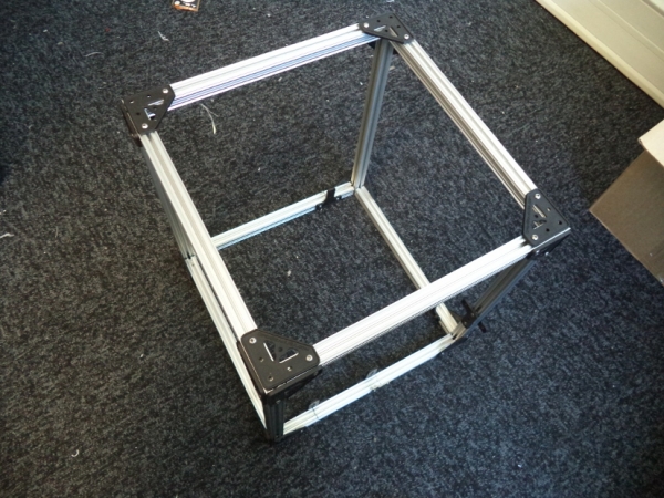
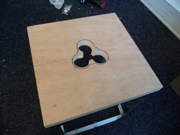
Cover the frame with the wooden plank. With the use of the electric drill, cut suitable holes in the shape of the base rigid platform of the manipulator, so that there is easy access to the connection holes of the sockets and also the cable guides.
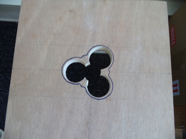
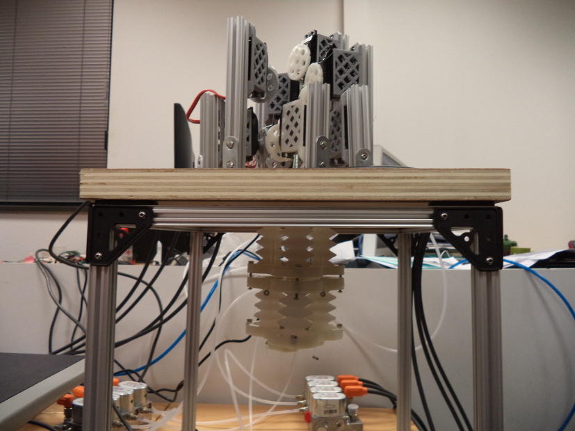
Finally, attach the plank to the frame using bolts from the bottom up. The servos will be placed on top of the cover, while the manipulator will be attached to the plank at the bottom side. The manipulator will be operating hanging from the cover of the base.
Fabrication: A step-by-step guide (part 3)
Final assembly
Once all the parts of the manipulator are fabricated, we can start the final assembly of the robot. The first step is to attach the base platform to the bottom of the plank in the base frame. As explained before, long bolts of Ø4mm and nuts are used to fix the platform.
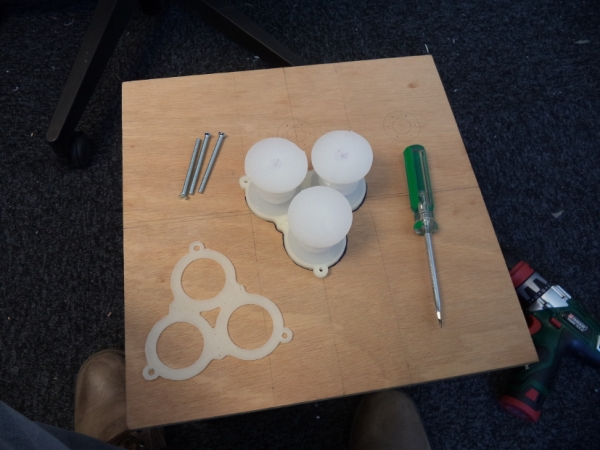
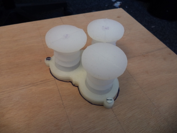
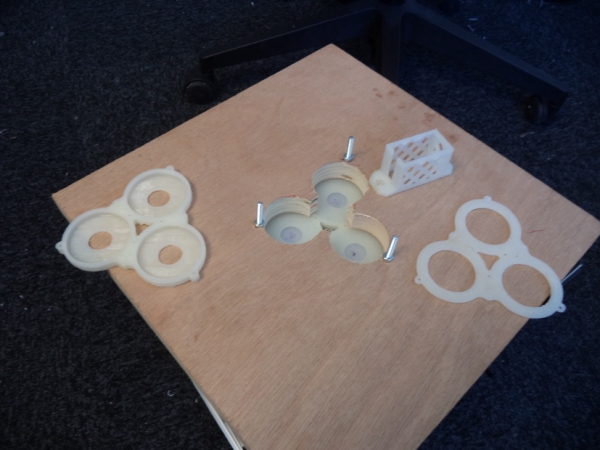
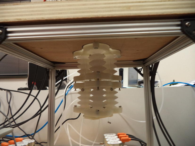
The next step is to connect the second section to the first one. 30mm long Ø2.5mm bolts are used to attach the two parts of the middle rigid platform; this was done with the objective of having a small gap between the two parts of the middle platform, so that the tubes that supply the air to the second set of pneumatic actuators could have some room to bend.
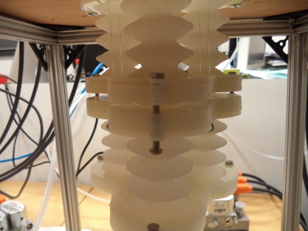
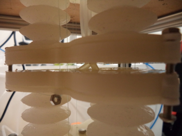
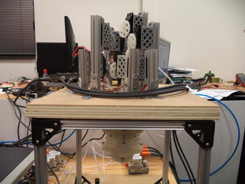
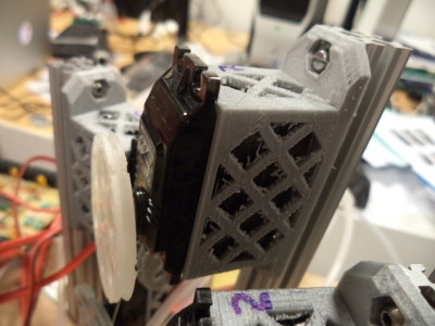
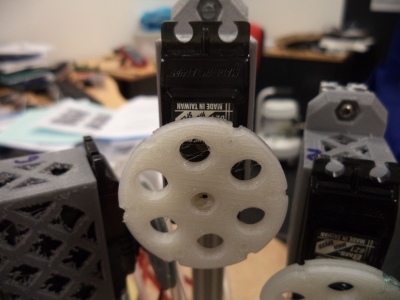
With both sections in place, we can start putting the cables through their dedicated holes. There are six cables in total, three of them go from the base to the middle platform, while the other three go from the base to the top platform. The cables are actuated by servos placed on top of the base cover. Special care is needed while putting the servos in place, to make sure that the pulleys attached to the servos are aligned with the cable holes at the base platform. Nuts were tied up at the end of each cable so that the cables can apply forces to the platforms.
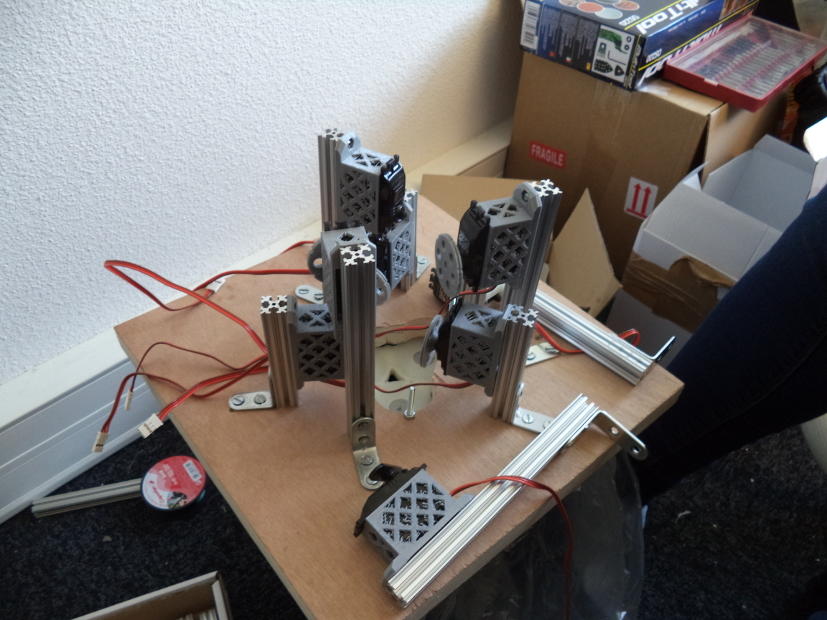
After every part is in its place, the robot looks like this:
