Testing
This section provides some explanations about the method we use to control the robot and test its expected behavior. Videos of the different tests made at each part of the fabrication and the piloting of the final robot with a real-time comparison to the simulation of its behavior is also presented.
Model and Control
The robot is composed of 6 pneumatic actuators and 6 cables. The robot is thus highly redundant and composed of hybrid actuation.
To drive the 12 actuators in a coherent manner, a new approach is needed for control. Bosman et al. recently proposed a method dedicated to continuum robots with rigid vertebrae. One important contribution of this work is to demonstrate that the method of control can be extended to hybrid and redundant actuation.
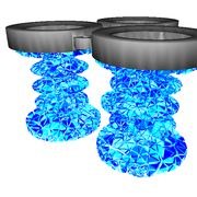
The first step of the method is to build a detailed FEM model of one intervertebra attached to a vertebra. For that, we use SOFA and the plugin dedicated to soft robots. The simulation is able to mix deformable and rigid parts, thanks to a generic definition of the degrees of freedom available on SOFA platform.
The second step is the heart of the method: to avoid computation burden and allow for real-time computation of the robot model, we use a model reduction method based on a domain decomposition approach. The algorithm computes the equivalent non-linear stiffness of the intervertebra.
 |
|
|
| → | ||
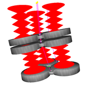
The third step consists in building a simplified model of the whole robot and placing the cables. To compute a motion of the cavities with no precise simulation of the intervertebra (because we are using a simplified model), we use a technique often used in computer graphics that is called skinning. From the 6D frame of each intervertebra, the skinning provides a deformable motion of the inner cavity. In SOFA, we can reverse this skinning as done in [Duriez et al 2008] to compute the equivalent force on the frame, due to the pressure applied on cavity walls.

The last step is to launch the inverse control method, presented in [Duriez 2013] and extended in [Bosman et al. 2015]. It consists on inverting the deformable model, thanks to an optimization method and finding the actuator value given the desired position of the effector (here we control all the degrees of freedom (DOF) of the effector, except the twist, so 5DOF). As the robot is highly redundant, we add more criteria in the optimization to get a single solution to the problem: the method minimizes the pressure value (to put as little pressure as possible in the cavities) and it also minimizes the energy of deformation.
Actuator and platform testing
Along with the fabrication phase, the performance of the pneumatic actuators was tested, as well as the real behavior of the "Stewart platform"-like section of the manipulator.
The initial test conducted on a 5cm long actuator showed that a maximum extension of 47% (2.35cm) could be obtained when a pressure of 0.3 bars is applied. If the cavity pressure increases further, the actuator deforms radially. It is then important to operate the actuator inside the pressure range of 0 – 0.3 bars.
|
|
A preliminary test of the real behavior of the pneumatic based Stewart platform was conducted. This test was done without the cable actuators.
|
|
Robot piloting based on FEM simulation
The modeling method and simulation described previously to pilot the robot was used. The inverse model is computed in real-time to obtain the actuation required to orientate and position the manipulator as desired. This position is controlled by moving manually a control point attached to the top platform in the simulation.
The first test was conducted using only cable actuation.
|
|
In the second test, antagonistic (both cable and pneumatics) actuation was implemented in the simulation.
