Soft Robotics for the Hobby Roboticist
Introduction
The basis for this project is the robotic hand article Andrew Terranova contributed to the Manual section of Popular Science magazine, based on the techniques outlined in Harvard's Soft Robotics Toolkit.

The goal of this robotic hand project is to make soft robotics accessible to the hobby roboticist. Some of the tools, materials and techniques included in the soft robotics toolkit may be somewhat challenging or expensive for a hobbyist. This project aims to use simpler techniques, common tools and less expensive material whenever possible.
The video below demonstrates the performance of the hand and the control board.
Designer

Andrew Terranova is a program manager, electrical engineer and an electronics and robotics hobbyist. He is an active member and supporter of the Let's Make Robots community.
Andrew is also a freelance writer. In addition to the Popular Science article for the robotic hand project, he has worked as a contributing editor for Make:, contributing several articles to the print edition of Make: Magazine and numerous posts and projects to their blog.
Background
While discussing a topic for an article with Popular Science editors, the Harvard Soft Robotics Toolkit was mentioned. Andrew Terranova had seen the toolkit before, but had not considered making something with it. Andrew reviewed the information in the toolkit, and decided to adapt some of the concepts to make a robotic hand.
Goals
Some of the materials and fabrication techniques included in the toolkit seemed intimidating for a hobby roboticist. To make soft robotics more widely accessible, the goals of this project were:
- Keep the project low cost
- Use easily available materials
- Use techniques that most hobbyists would find not too difficult
The resulting design met these goals, and was published in the May issue of Popular Science.
Below is a video excerpt from Erin Kennedy's Robot Party Google Hangout from February 2015, where I introduce the project and explain some of the motivation behind it. The Robot Party is a community group of robot makers who meet online to demonstrate and discuss robotics projects.
Requirements
Although there were no formal functional requirements, an important aspect of the project was to create an engaging exhibit to attract and interest people into soft robotics. On April 19th 2015, Andrew displayed the robotic hand at the Children's Museum of Somerset County NJ, where he volunteers, much to the delight of the children and not a few of their parents. It is hopeful that the project will continue to inspire curious people to try something in robotics in general, and soft robotics in particular.

Design
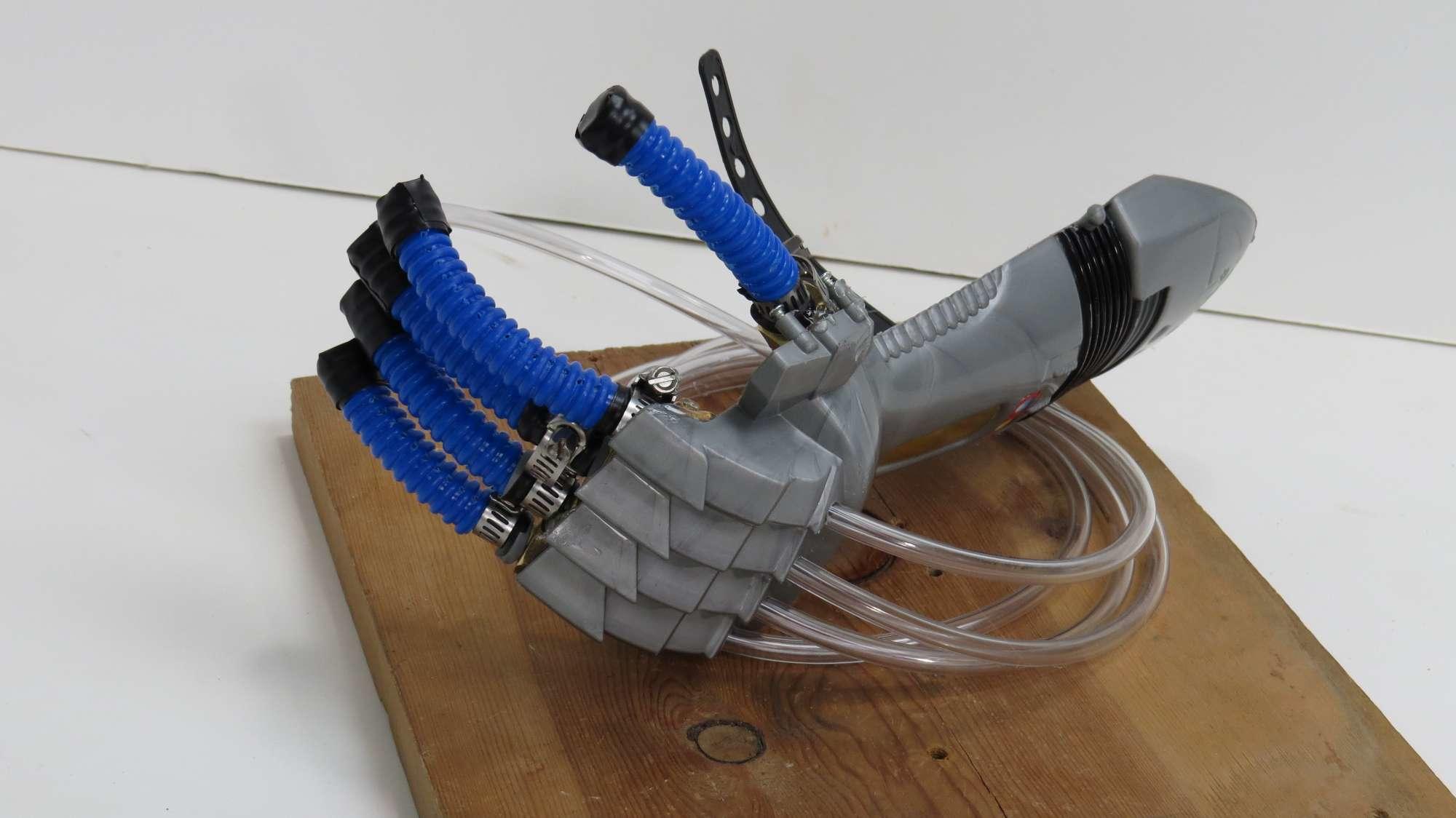
The design for the actuators of the soft robotic hand is based on the concepts of fiber-reinforced actuators, but the materials and fabrication techniques are much simpler. Ribbed plastic hose, of the kind found on inexpensive foot pumps, is used as the reinforcing material.

A standard latex 350Q balloon, the kind used for making balloon animals and available at any party store, is used as the inner bladder.

There is a clear trade-off in reliability, as many of the fingers eventually failed... sometimes quite comically as the balloon expanded through the failed plastic of the constraining ribbed hose (see Actuator Testing and Performance section). Nevertheless the low cost and ease of fabrication make this a reasonable option where reliability is not a key factor. It is fairly easy to make a new finger to replace a broken one as needed.
Each actuator forms a finger, which was combined to make a completed hand by fastening to a toy armor gauntlet that happened to be available.

The subsections will outline the design of the individual actuators, the hand as a whole, and the control board.
Actuator Design
Balloons of the type used for twisting animals and other fun things for kids seemed the clear choice of material for the inner bladder. The 350 type balloons (3 inches wide, 50 inches long) were chosen over the 260 type (2 inches wide, 60 inches long) most commonly used for twisting balloon shapes. The 350 balloons felt more durable than the 260s; the latex may have greater wall thickness. These balloons are easily available and suited the purpose well.
The selection of the reinforcing material, however, took considerable trial and error. PVC tubing of various sizes and types, and even latex reinforced work gloves were tried. The standard PVC tubing split easily, while the braid reinforced type was too hard to bend. The gloves did not provide enough structure. In the end, what worked best was a ribbed plastic hose that came from an inexpensive foot pump. This is the blue hose shown in the picture below.

The hose has a slight natural bend to it, similar to a human finger when held at rest. Stress relief holes are used on each side of the hose between each rib to reduce the chance of the hose splitting. Slices between each rib along the upper side of the curve, extending to the stress relief holes, allow the finger to bend when the balloon is inflated.

The tip of the finger is blocked so the balloon cannot expand in that direction. So when the balloon is inflated with pressurized air, the only way the balloon can expand is by bending the finger.
Hand Design
The design is a simple analog for a human hand. For simplicity, a plastic toy armor gauntlet was used as the platform for the five actuators. One happened to be available. A simple wooden board or other platform would have served, but wouldn't have looked as nice.

The thumb is opposed to the fingers as in a human hand. This allows for some gripping capability. However, because all the fingers are fixed with only the ability to flex as their movement, the effectiveness of the gripper is limited. In a human hand, there are many more degrees of freedom, of course.
Control Board Design
The design of the control board was based on the fluidic control board in the soft robotics toolkit.
A few key differences to note are:
- Pressure sensors were eliminated to reduce cost.
- An 8-valve manifold was used to leave room for future expansion.
- Instead of an on-board compressor, an off-board workshop air compressor supplies the necessary pressurized air.
- Power is provided by one 12V DC and one 24V DC supply.
- A sensor shield (daughter board) was used with the microcontroller to make electrical connections easier.
- Five potentiometers (one for each finger) provide manual control over each actuator.
- One potentiometer allows you to vary the Pulse Width Modulation (PWM) frequency used to control the flow of air to the actuators.
- A toggle switch allows you to either select manual control with the five potentiometers, or programmed control.
- A 12-position rotary switch lets you select between twelve different hand positions and gestures.
- Choice of black for the color is much cooler.

Fabrication
The following subsections provide step-by-step instructions for fabricating the individual actuators, the hand as a whole, and the control board.
Actuator Fabrication
Detailed steps to fabricate the actuators are below, but can also be found on the Popular Science website.
Materials
- 7/16-inch inner diameter ribbed hose
- 5/16-inch wood dowel
- 1/4-inch outer diameter vinyl tubing
- Small hose clamps
- 1/4-inch hose barbs x 1/4-inch male threaded adapter
- 1/4-inch hose barbs x 1/4-inch female threaded adapter
- Electrical tape
- Yellow Teflon thread tape
- Long balloon (type 350Q)
Tools
- Utility knife
- Spring-loaded center punch
- Drill press and 5/64-inch drill bit
- Scissors
- Flat head screwdriver
- Hot glue gun
- Measuring tape
- A couple of adjustable crescent wrenches
Assembly
- Insert the 5/16-inch dowel into the ribbed hose to hold it straight. Use the center punch to carefully punch holes between each rib in a line along the seam of the hose. Flip the hose over and repeat along other seam.

- Use the drill press to drill a hole at each center-punched location between the hose ribs, leaving the dowel in place to provide support. It is best to drill the holes on each side of the hose separately, rather than drill straight through. When you are done you should have a neat line of holes on each side of the ribbed hose. These holes will act as a stress relief and prevent the hose from splitting when it is flexed.

- Remove the dowel and cut the hose into five 3-inch fingers with the utility knife. For each finger, use the utility knife to very carefully cut between each rib from the hole on one side to the hole on the other. Leave the first two ribs on each end uncut. Cut through one side of the hose only. It is critical that you do not nick the far side of the stress relief holes or you will reduce the reliability of the finger dramatically. Now the hose can flex in one direction more than in the opposite direction.

- Insert another piece of dowel into one of the long balloons. Use it to gently feed the balloon into one of the fingers until the end of the balloon sticks out enough to grab it. Remove the dowel, and fold about 1/4-inch of the balloon tip over the rim of the hose. Secure it by wrapping a piece of electrical tape all the way around the tip of the finger.

- Now feed the dowel back inside the finger from the non-taped end, but on the outside of the balloon. Insert it until it is just within two ribs of the tip of the finger. Fill the tip of the finger with hot glue, allow to cool, and then carefully remove the dowel. It was found that the fingers were more reliable when a small amount of hot glue was used to fill the tip of the hose and then secured with more electrical tape. This helped prevent the end of the finger blowing out during use.
- Use electrical tape over the end of the finger, covering the hot-glued end. Another wrap of electrical tape over this will seal the end of the finger.

- Cut the open end of the balloon away, leaving about an inch beyond the end of the finger. Stretch the open end of the balloon out and over the end of the finger.

- Repeat steps 4 through 7 for each finger.
- Use the yellow Teflon tape to wrap the threads on each of the male hose barbs. Thread each male hose barb onto each female hose barb and tighten firmly with the crescent wrenches. Then use more yellow Teflon tape and wrap each female hose barb several times around. The ends of these hose barbs should fit snugly into the open ends of each finger.

- Use the small hose clamps to affix each finger onto the Teflon wrapped ends of the five hose barbs.

Hand Fabrication
Detailed steps to fabricate the hand are below, but can also be found on the Popular Science website.
Materials
- 1x6-inch board or other support material
- 1/4-inch O.D. vinyl hose
- Tape
Tools
- Hot glue gun and glue sticks
- Drill and drill bits
Assembly
- Use hot glue to firmly attach each finger to the end of the 1x6-inch board or other support (the prototype used a plastic toy gauntlet) to form a hand. (see picture)
- Attach a length of 1/4-inch O.D. vinyl hose to the open hose barb on each finger.
- Secure the hoses to the board or other support using tape, or drill holes to allow the PVC tubing to be routed.
- Now the hand is complete, but it still needs a control system. Follow the instructions for the Control Board Fabrication.
Control Board Fabrication
Detailed steps to fabricate the control board are below, but can also be found on the Popular Science website.
This is a complex project. Since your control board is a considerable investment in time and money, consider future expansion as you plan your build. For example, you may wish to buy an 8-port manifold and appropriate valves and fittings, so you can expand the board to control more actuators than then five you need for the robot hand project.
You can download the schematic below from the link at the bottom of the page. Clicking on the image below will also load the image in your browser, and you can save it locally from there.

Materials
- Air compressor with regulator
- 1/4-inch Sintra PVC board (12-inch x 24-inch)
- 24V 15A DC power supply
- 12V 1A DC Power Supply with size “M” 2.1-mm x 5.5-mm coax connector
- Panel-mount coax power jack, size “M” 2.1-mm x 5.5-mm
- Coax power plug, size “M” 2.1-mm x 5.5-mm
- Arduino Mega 2560 or compatible
- Sensor Shield for Arduino Mega V2 (with cables)
- Two YourDuino Power FET switch boards
- Five SMC VQ110U-5M-M5 air valves (or similar: 24VDC, connector with lead wires)
- One SMC VV3Q11-05 5-port manifold (or similar)
- Six SMC KQ2L07-M5 elbow fittings
- 1/4-inch outer diameter vinyl tubing
- Six 50-kilohm potentiometers (“pots”)
- Seven 6-mm shaft potentiometer knobs
- 22 gauge stranded or pre-bonded wire (black, red, and yellow)
- 24 gauge multi-conductor cable or ribbon cable (13 conductors needed)
- 6-gang terminal block
- Three single pole double throw toggle switches
- Two 5-mm yellow LEDs
- Two 5-mm LED mounts
- 560-ohm resistor
- 1.2-kilohm resistor
- Twelve M 3-mm x 6-mm Phillips plastic PCB board fasteners
- Twelve 21-mm x 6-mm PC board spacers
- Five 1/4-inch 2-inch hex bolts
- Ten 1/4-inch hex nuts
- Two 10-32 1-inch bolts
- Double sided foam tape
- Shrink tubing
- Wire zip ties (for cable management)
Tools
- Table saw
- Pencil
- Center punch
- Drill and drill bits (13/64", 17/64", others sizes based on component dimensions)
- Metric tap M 3-mm x 0.5-mm, standard 10-32-inch tap (other sizes based on component dimensions)
- Soldering iron and solder
- Wire stripper
- Flathead and Phillips screwdrivers
- Adjustable wrench
- Lighter (for shrink tubing)
Assembly
- Lay out the control board. You can base your design on the photos, but adjust it to suit your own needs. It is convenient to have the power and controls near the edges where you can reach them. It is also convenient to have the Arduino Mega/Sensor Shield between the controls and the MOSFET power switches. The MOSFET modules should be close to the air valves/manifold. Power supplies can be placed wherever you like, but consider how power will be routed around the board.

- Cut the Sintra board using a table saw to a size to fit your layout. 12 inches by 16 inches should do. This will be the base of the control board.
- From the remaining Sintra board, cut one piece for mounting the controls (about 12 inches by 2¼ inches). Cut another piece for the power switches and indicators (about 2 inches by 6 inches). Cutting a curve on one side of each of these pieces lets you fit them more compactly on the base, and adds a touch of style.

- Use a pencil and a center punch to mark holes on the two mounting boards for the 50-kilohm pots, switches, LEDs, power jack, and for the hex bolts that will mount the boards to the base.
- Drill the holes in the mounting boards. It is possible to tap threads into Sintra board if you want to screw the pots directly into the board, rather than use nuts to hold them. Use one “sacrificial” pot as the tap, if you don’t have the proper size tap to cut the threads (this may damage the pot).
- Use hex bolts and nuts to raise the two mounting boards above the base. Before you install any components in the mounting boards, line them up on top of the base where you want them. Using the holes you drilled for the hex mounting bolts as a guide, mark the base. Then drill 13/64-inch holes in the base and make threads using a 1/4-inch by 20 tap.
- The Arduino Mega and the MOSFET switches should be mounted using M 3-mm x 6-mm Phillips plastic PCB board fasteners. Mark, drill, and tap holes to mount them and the other components. The 24V power supply may be mounted with double-sided foam tape. The air manifold can be mounted with two 10-32-inch bolts or with the foam tape.
- Mount the 24V power supply, air manifold, MOSFET switches, Arduino Mega and Sensor Shield, and 6-gang terminal block to the base. The terminal block may be mounted with small self-tapping screws or with foam tape.
- Mount all the pots, switches, LEDs, and the power jack to the two mounting boards, but don’t mount the boards to the base yet. You have some soldering to do first.
- The schematic shown at the top of this page can also be downloaded so you can refer to it in higher resolution. Refer to the schematic to wire the six pots, the 12-position switch, and the SPDT switch on the control mounting board. Connect the wires as shown to the Arduino Mega Sensor Shield.

- Follow the included schematic to wire the 12V power jack, power switches, and LEDs for the power mounting board. Connect the wires as shown to the 6-gang terminal block. Wire the 24V power supply as shown, and connect the 12V power jack. Leave the power supplies unplugged from the AC wall socket for now.
- Mount the control and power boards to the base board using 1/4-inch hex bolts and nuts. For each bolt, set one nut flush to the base board and another flush to the mounting board from underneath. This will hold the mounting board firmly.

- Run power from the 6-gang terminal block to the Arduino Mega and MOFSET switches. Check the schematic for details.
- Connect the digital out pins of the Arduino Mega Sensor Shield to the input channels of the MOSFET switches as shown in the schematic. Then wire the channel outputs of the MOSFET switches to five of the SMC air valves.

- Connect the 1/4-inch outer diameter vinyl tubing from the five air valves to the robot hand. Connect more 1/4-inch tubing from the input of the air manifold to your air compressor. You should set the output of your compressor to about 20 pounds per square inch. You may need to adjust the pressure from the air compressor to slightly more or slightly less, but this is a good starting point.

- Plug in the 12V and 24V power supplies. Turn on the 12V supply power switch only (for now).
- Download the the software sketch example in the attached text file. Change the file extension from .txt to .ino. Set up your Arduino programming software, connect to the Arduino Mega, and then compile and download the sketch to the Mega.
- Now turn on the 24V power switch. With the function selector switch in one position, you should be able to control each finger with one of the five pots. Try adjusting the duty-cycle pot to different positions and see how it works. With the function selector switch in the other position, the 12-position switch will control the position or motion of the hand.
Testing and Performance
The robotic hand was not designed to meet a specific set of requirements or capabilities. Rather, the idea was to create a soft robotics project that would be accessible to a wider audience. Performance of the soft robotic hand has been acceptable, based on the goals of the project.
- Keep the project low cost
- Use easily available materials
- Use techniques that most hobbyists would find not too difficult
The resulting design was published in the May issue of Popular Science.
The video below demonstrates the hand and control board operation.
The following subsections will discuss performance observations of the individual actuators, the hand as a whole, and the control board.
Actuator Testing and Performance
The video excerpt below is from Erin Kennedy's February 2015 Robot Party, where I discuss the reliability of the finger actuators. The Robot Party is an online community of robot makers who share their projects and discuss robotics ideas.
Materials
As mentioned in the design section, several different materials for the fingers were tried. The ribbed hose selected for the prototype worked the best. However, it is far from perfect. The fingers do fail after repeated use. Others are encouraged to investigate other materials and techniques.
Reliability
Sometimes the tip of the finger blows out, as shown in the picture below, or it fails along the length. These failures are caused when the plastic fatigues and one of the cuts in the finger splits beyond the stress relief holes.

Potential Modifications
A 3D printed design to replace the ribbed hose is an interesting option. The growth of 3D printing has made a custom designed actuator a reasonable possibility for a hobbyist. The ability to manipulate design parameters and rapidly prototype for increased reliability is very attractive.
This project will be updated if a workable solution using 3D printing can be developed.
Hand Testing and Performance
The video below is an excerpt from Erin Kennedy's February 2015 Robot Party. The Robot Party is an online community of robot makers who share their projects and discuss robotics ideas. In the video I demonstrate the manual and programmed modes of operation, and discuss the performance of the gripper.
Gripper Performance
As a practical gripper, the hand has very limited use. The fixed position of the fingers makes it much less flexible than a human hand, while the soft materials make it much less precise than a traditional robotic gripper. In effect... the worst of both worlds!
The hand can hold light objects like a ball or a light weight hand tool. It could be attached to a larger robot arm as an end effector, and used in situations where precision and grip strength are not as important as having a gentle, compliant grip.
Gesture Performance
Much of human communication is non-verbal. By using gestures that humans are familiar with, a robot can elicit an emotional response. For example, different responses from an observer are likely if the robot is gently waggling its fingers, taping impatiently, imitating a rude gesture, or ominously counting down.
Programmed Mode
In programmed mode, the several gestural positions and programmed motions can be amusing, and are instructive as an example of what soft robotics can do. Additional positions and motions can be programmed as well.
Manual Mode
When operating in manual mode, the frequency of the Pulse Width Modulation (PWM) used to control the air valves can be changed via a potentiometer. The frequencies used are in the audio range and sound is emitted by the coils of the air valves during use. The frequency also visibly alters the movement of the fingers from a stuttering motion to a fairly smooth motion.
Within the limits of the freedom of motion, the hand can be made to "dance" and "sing" along to the control of an operator, which can be somewhat entertaining.
Control Board Testing and Performance
The video below is an excerpt from Erin Kennedy's February 2015 Robot Party. The Robot Party is an online community of robot makers who share their projects and discuss robotics ideas. In the video I demonstrate the control board, and also discuss how this project can be a jumping off point for people interested in using the soft robotics toolkit.
The control board performed very well. As mentioned in the design section, there are certain differences between the prototype and the fluidic control board design defined on the main Soft Robotics Toolkit.
- Pressure sensors were eliminated to reduce cost.
- An 8-valve manifold was used to leave room for future expansion.
- Instead of an on-board compressor, an off-board workshop air compressor supplies the necessary pressurized air.
- Power is provided by one 12V DC and one 24V DC supply.
- A sensor shield (daughter board) was used with the microcontroller to make electrical connections easier.
- Five potentiometers (one for each finger) provide manual control over each actuator.
- One potentiometer allows you to vary the Pulse Width Modulation (PWM) frequency used to control the flow of air to the actuators.
- A toggle switch allows you to either select manual control with the five potentiometers, or programmed control.
- A 12-position rotary switch lets you select between twelve different hand positions and gestures.
- Choice of black for the color is much cooler.
User Interface
The controls knobs and switches are all located on the outer edges of the board so they are easy to reach. As I built the prototype for myself, nothing is labeled. I did find that when I invited others to use it, the controls were fairly intuitive. Even children quickly learned how to operate the hand.
Expandability
The use of an 8-port manifold allows for controlling more pneumatic actuators. Actuators could be added to move control a robotic arm or to add additional degrees of freedom to the existing hand.
Because the current control panel is fully populated, it may have to be replaced or modified if additional actuator control is desired.
The programmable nature of the Arduino Mega microcontroller allows for plenty of software expandability.