Demo 4: Shell-Reinforced Linear SPA
1. ACTUATOR GEOMETRY
The models for linear shell-reinforced actuators are available open-source here.
In these actuators, a single air chamber is modeled for providing enhanced mechanical reliability of the actuator by eliminating stress concentrations at narrow passage walls. Furthermore, the cross-section of the air chamber is circular in this case as compared to the square cross-section for multi-chamber actuators described in other demos. The linear actuator achieves linear motion due to the corresponding shell pattern discussed earlier in the design section. Due to the symmetry of the structure, only half the portion of the entire actuator is created and modeled.
The geometric parameters of the actuator, such as the length and diameter of the chamber, the wall thickness, and the cut spacing on shell surface can be customized using the models provided.
As an example, the following geometry is generated in Abaqus CAE for a linear actuator with outer diameter of 4 mm, wall thickness of 2 mm and total length of 40 mm. The number of cuts on shell surface is 13, at a cut spacing of 0.5 mm.

2. MATERIAL CONSTITUTIVE MODEL
The elastomers typically used to create soft actuators exhibit hyperelastic behavior. The design tool provides the ability to model this behavior using several well-established constitutive laws (for a complete list, please see the scripts section). In addition, the user has the option to include viscoelastic behavior as well to capture any time dependent effects. For this example, the chamber is made in Exoflex-30 material while the thin un-stretchable shell layer is made of a plastic material such as PET. The material Ecoflex-30 is modeled using a hyperelastic model while the shell is modeled using a linear elastic model (due to stresses in shell not exceeding elastic range), as shown in images below. A 3-term Ogden model is used for Ecoflex-30 in this example, with the following coefficients:
mu1 = 0.001887; alpha 1 = -3.848; mu2 = 0.02225; alpha2 = 0.663; mu3= 0.003574; alpha 3 = 4.225; D1 = 2.93; D2 = 0; D3 = 0


3. PRESSURE LOADS
In this example, an input pressure of 50 kPa was specified on the chamber walls. The following figure shows the corresponding load application in the Abaqus CAE file generated.

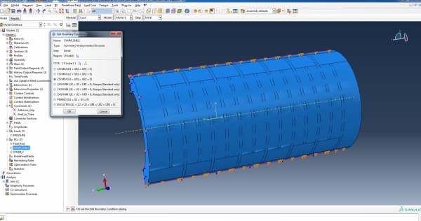
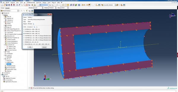
4. BOUNDARY CONDITIONS
The boundary conditions include half symmetry, as mentioned previously, and no translation or rotation for the inlet portion. The corresponding images are shown below.

5. INTERACTION
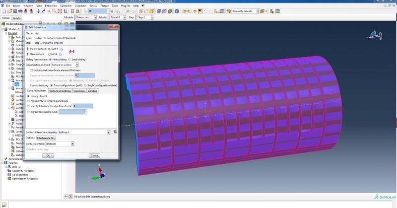
In this design, the shell is permitted to slide over the surface of the actuator and guide its trajectory. To implement this condition in Abaqus, a contact property is defined to include finite sliding in tangential orientation with a specified coefficient of friction, as shown below.
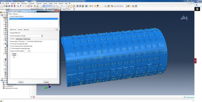
Surface-to-surface contact is then defined between the shell and the actuator surface using the contact property defined above, as shown in the image below.
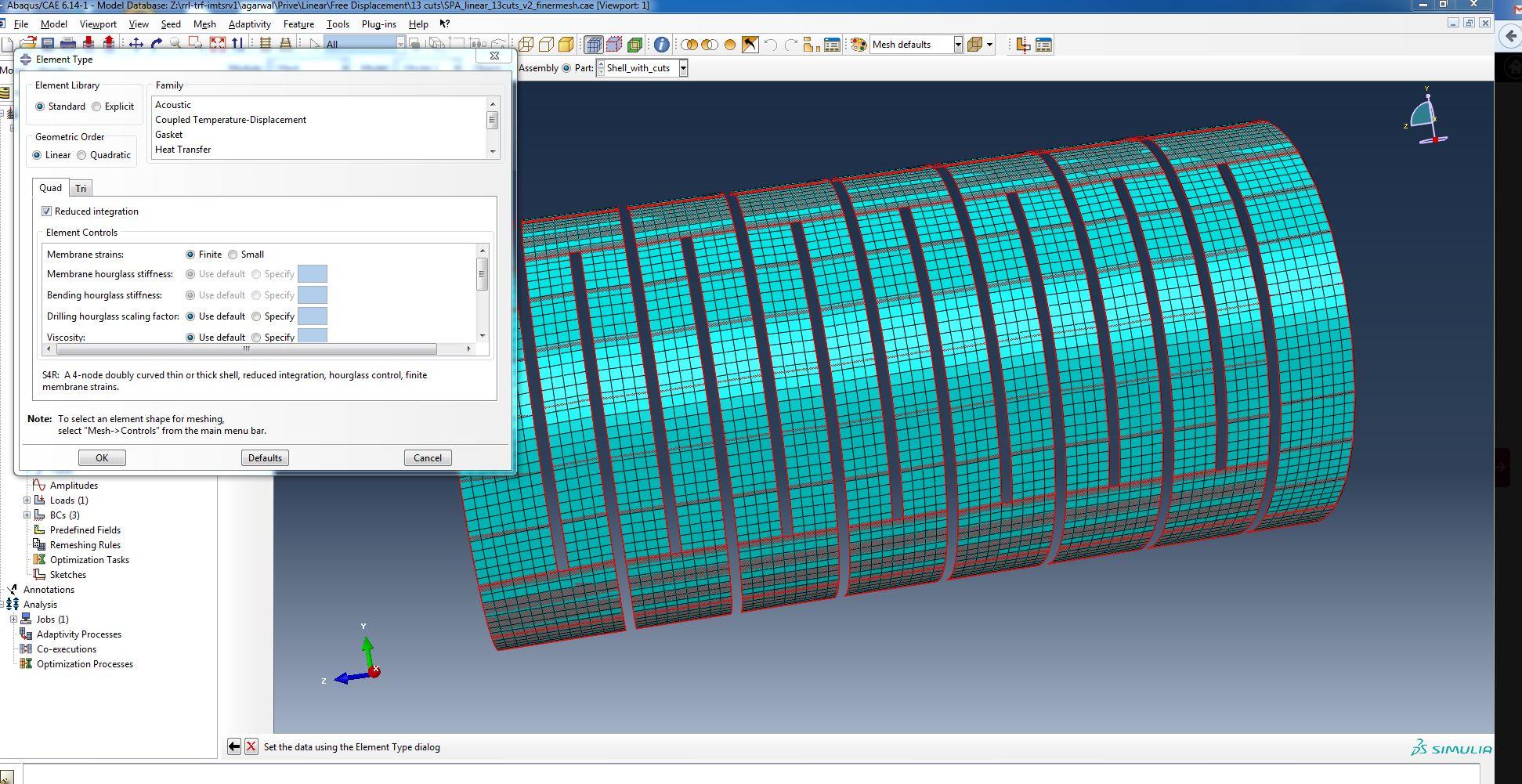
6. MESH GENERATION
In this case, due to the hyperelastic behavior of the material used to create the actuator core, standard linear 3-D stress elements are used with hybrid formulation and reduced integration. This ensures that any issues associated with shear or volumetric locking are avoided and that large deformations are permitted, as is expected in the case of the materials implemented for these actuators. For the shell structure, standard linear shell elements with reduced integration are used. The following image shows the mesh generated for the shell, as an example.
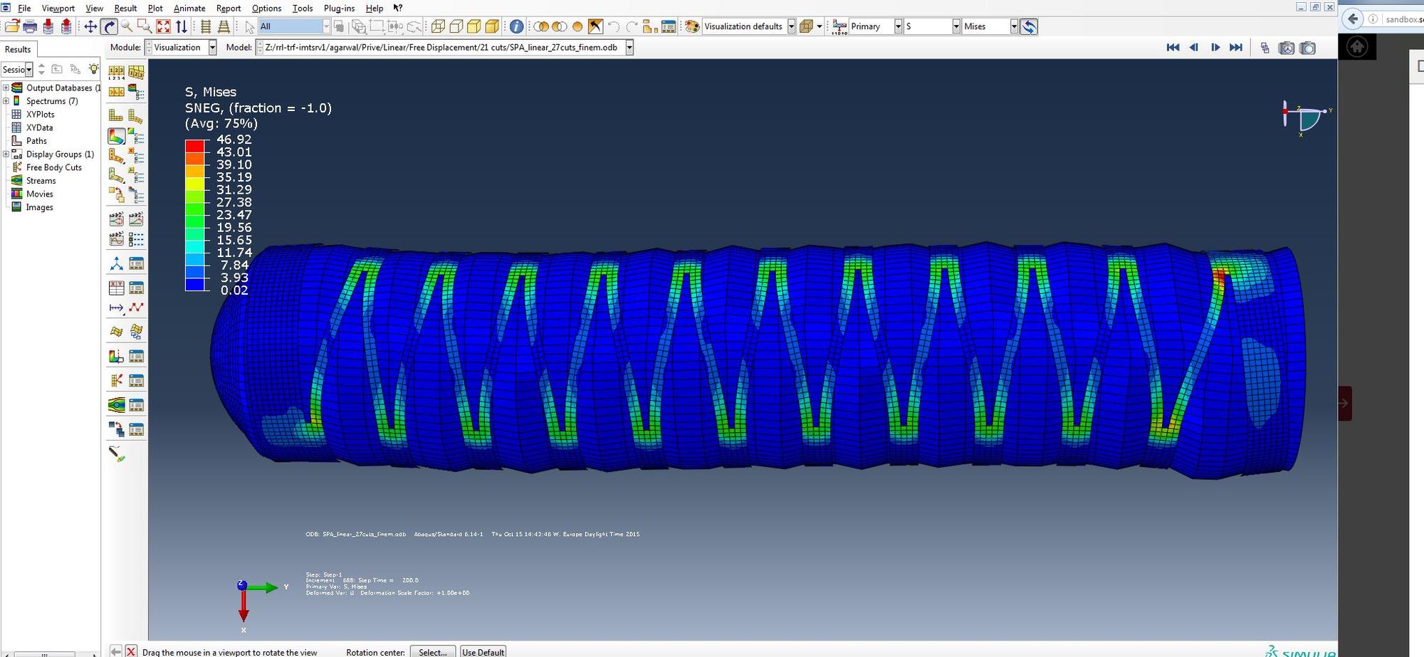
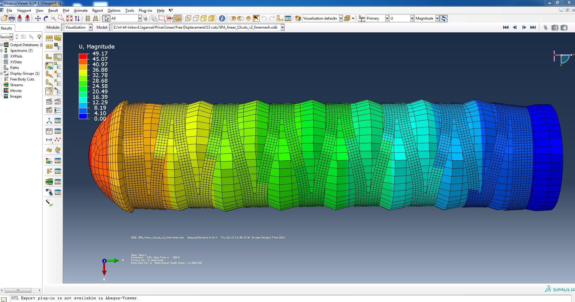
7. OUTPUT ANALYSIS
A variety of analysis can be performed using the design tool, including evaluation of the actuator performance under free and blocked loading conditions. Abaqus ODB result plots for linear extension motion generated are shown below for the free displacement condition.
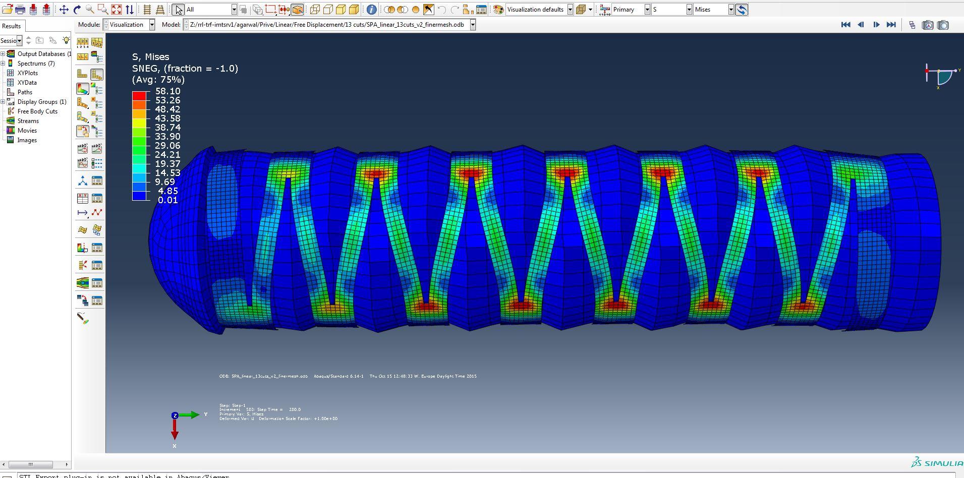
It is seen that the stress concentration occurs at the notches in the shell structure. This stress can be reduced by increasing the number of cuts on the shell surface. The following image shows reduction in stress obtained for the case of an actuator with 21 cuts on shell surface, as an example.