Fabrication
Soft Robotics Gripping fingers have been fabricated using Elastosil M4601 2-part silicone rubber with 1:9 composition and using 3D printed molds with due temperature conditions. Also the pneumatic control board has been constructed to control the shape of the soft robotics fingers by using flex sensor input. The Hand Gesture Control has been integrated and the fabricated procedure with relevant control variables and parameters will be discussed in the sub sections.
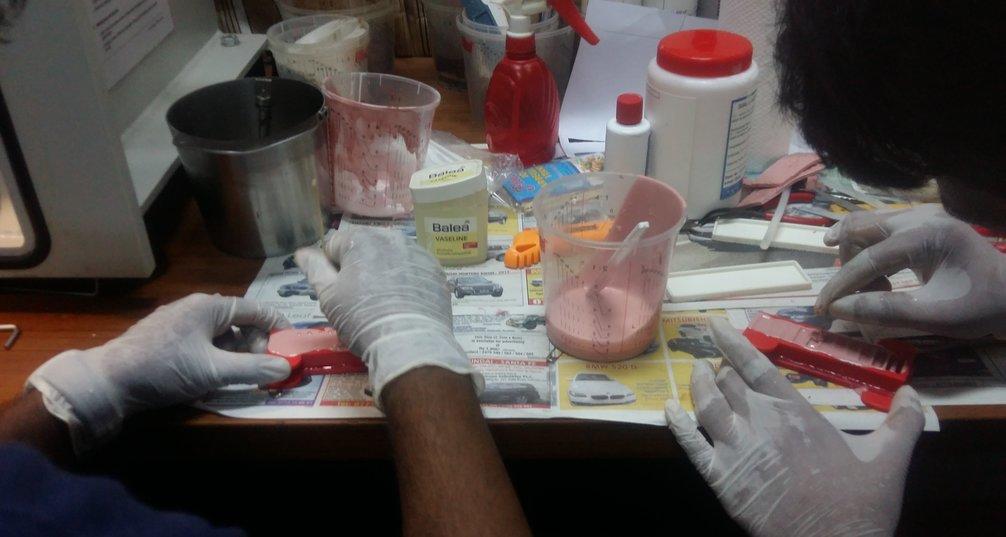
Soft Fingers
- Initially, Elastosil A and B in 9:1 ratio. 90g from part A (white) and 10g from part B (Red) were measured and poured into the mixing cup.
- Then the mixing cup was put into the centrifugal mixer and the mixing process was run until both materials mixed uniformly.
- The 2 parts of main mold were hot glued and the mixture was poured into the main mold.
- Then the mixture was poured into the base mold until half of its depth got filled with the mixture.
- After that the molds were placed in a vacuum chamber and the valve was slowly turned on.
- After the popping up of bubbles, the valve was slowly released and air was let back to the chamber.
- The bubbles were popped, using a barbecue stick that had not been drawn into the surface.
- Before putting the mold into the oven excess Elastosil was wiped off from the main mold and piece of paper was added on top of the Elastosil of the base mold.
- Later the both molds were placed in the pre-heated oven at 65°C for 15 minutes.
- While this procedure was repeated, the level of Elastosil in the chamber mold dropped at certain intervals. When this happened, extra Elastosil was poured and it was returned to the oven for another 15min for cure.
- Then both molds were removed from the oven and the top part of the actuator was removed from the mold. Then a fresh mixture of Elastosil was made, of 10g (9g of part A + 1g of part B) and a small amount of mixture was poured into the edge of the base mold. Then the top part of the actuator was placed on the base mold and edges were sealed using the extra Elastosil mixture. After that, the joint part was placed in the oven again for 15 minutes.
- Finally, the cured actuator was removed from the oven and the actuator was removed from the base molds.
Control Board
Fabrication of cast acrylic parts
300mm x 400mm x 4mm cast acrylic sheet has been used for top and base plate for the control board. Following figures shows the AutoCAD drawing of both top and base plates and this AutoCAD drawing was used to laser cutting process.
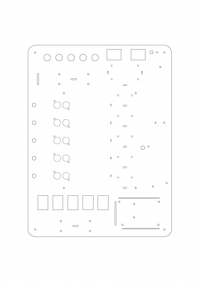
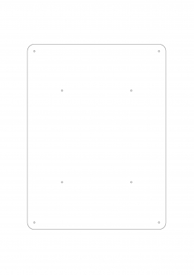
Main parts of the control board
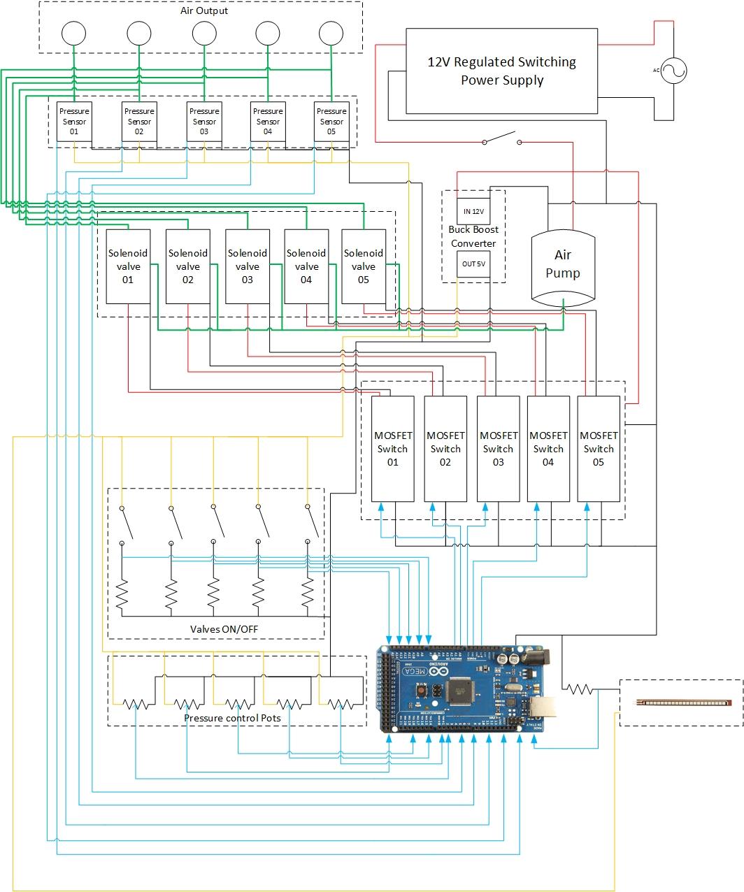
The below figures show the main parts which were used to develop the pneumatic control board.
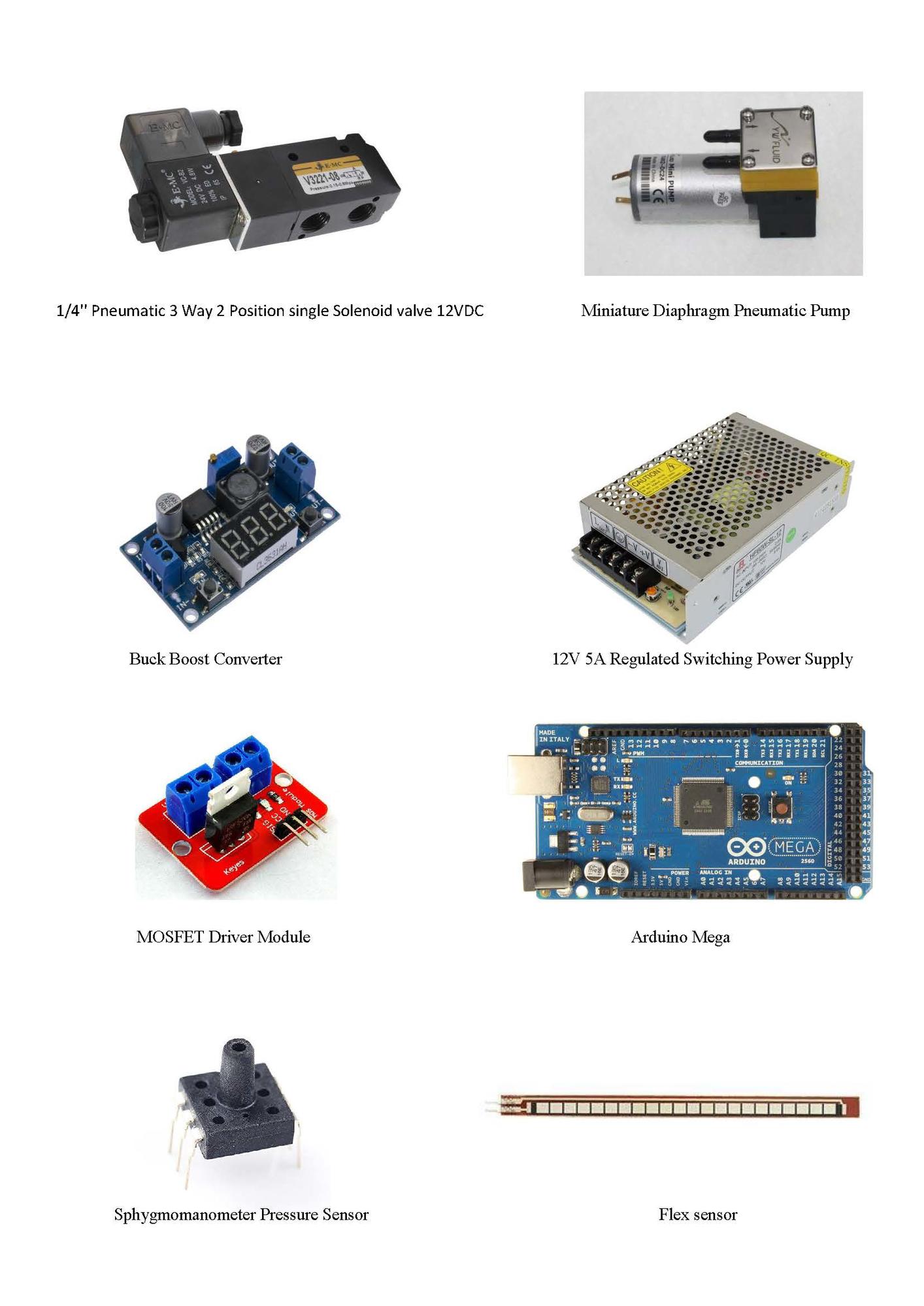 Wiring diagram of control board
Wiring specifications of the control board
Wiring Colour | Type of signal |
Red | 12vdc |
Orange | 5vdc |
Black | 0vdc |
Blue | 0-5vdc (logic) |
Green | Pneumatic |
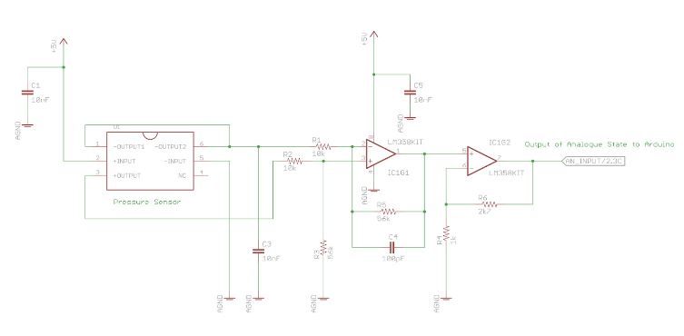
Circuit diagram of pressure sensor and differential amplifier
Following figure shows circuit diagram of Sphygmomanometer pressure sensor and differential amplifier’s connections. Pressure sensor has the capability of measuring a range of pressure values. It was driven by 5 VDC and 0-25 mV was the output signal. Therefore a differential amplifier circuit was used to amplify 0-25mV up to 200 mV to 3.5 VDC swing because the strength of the output signal was not sufficient to interface it with an Aruduino.
Hand Gesture Integration
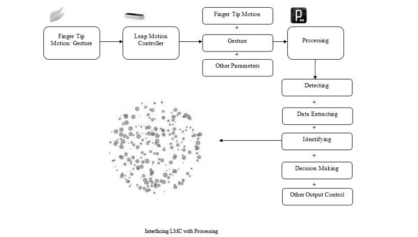
As shown in the above figure hands (includes palm and fingers) were detected by the Leap Motion Controller and data was sent to the Processing software. The processing software is capable of detecting, extracting data, identifying, decision making and other output controlling. This depends on the generated program. Once control decisions are made according to the application requirements, control algorithms, processing can instruct controller or other program to what should be done.
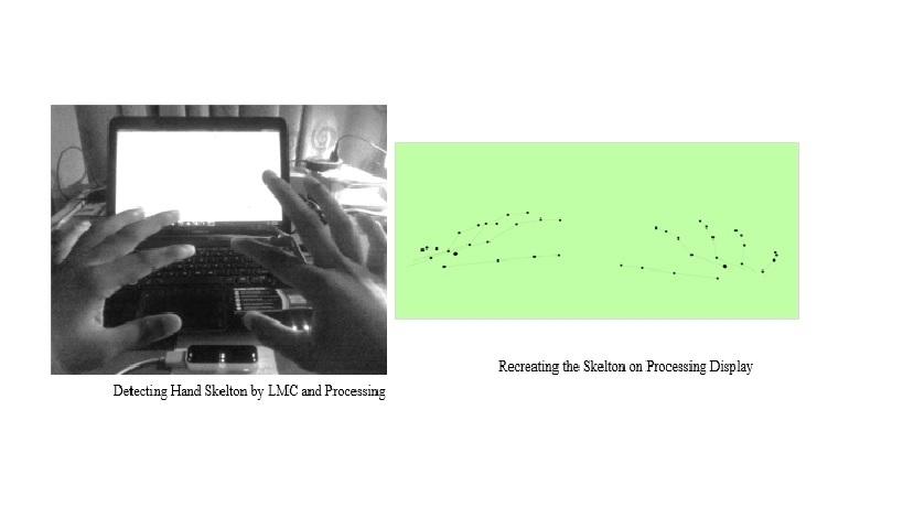
Above figure (right) shows the development of tracking two hands using processing. The skeleton of two hands were generated and shown in the above figure (left). The main design requirement of the application is to detect the fingertip and to extract the position, orientation and velocity data from it.
Therefore it is developed to track the middle, index and the thumb fingers. The tracked fingertips and wrist was recreated in the Processing framework as square objects and a circular object. The index finger was used to extract position, orientation and velocity data for the robot.
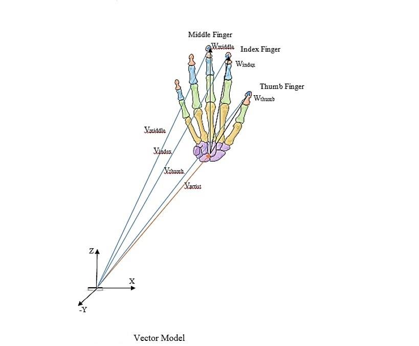
Then four vectors were drawn from the Leap Motion Controller coordinate frame to each fingertip and to the wrist. Then using the following relationship, a relationship to wrist to, fingertip distance was developed. The equation for the middle finger is as follows,
Vwrist + Wmiddle = Vmiddle
Wmiddle = Vmiddle - Vwrist
The same equation, was repeated for each finger and then took the average value as follows,
K = | Wmiddle |+| Windex |+| Wthumb | / 3
By that K parameter was generated, that will use to signal the solenoid valve. To control smoothly, the feedback was taken from the flex sensor attached to the soft finger and then was controlled according to the following pseudo code.
P = Flex Sensor
K is Initial Value
P is initial Value
P is Serial Analog Value Read
If P is Smaller Than or Equal K
Serial Digital Write High
Else
Serial Digital Write Low