Underwater Hydrojetting System
The Underwater Hydrojetting System is a project developed in the Organic Robotics Laboratory by Dr. Robert Shepherd's team at Cornell University.
The team developing is led by Robert Shepherd, assistant professor of mechanical and aerospace engineering. The project explores combustion potential in soft robotics.
The combustion chamber mimics the mantle of a squid, which inflates it rapidly and expels fluid in order to propel itself forward.
Hydrogen and oxygen gas is stored in the combustion chamber. Igniting the gas expands these internal chambers, alters the volume of the squid and thus propels it through the environment.
There are many applications to the successful development of this project, ranging from space exploration (many moons of Jupiter have liquid oceans and a soft robot would be very advantageous from mass and volume budget perspective).
More terrestrial applications of the soft robotics component of this research project include improvements to remotely operated underwater vehicles.
The bio-inspired technologies we propose to consider bypass the need to power rovers with limited-lifetime batteries, large solar arrays, or nuclear power. The rover also bypasses the difficulties of typical mechanisms in fluid through uniquely suited soft robotics. The expanding-gas locomotion concept is both exotic and eminently realizable, grounded in experimental work by our team.
Background

While most ocean life relies entirely on wave-like undulation to move through the water, the soft bodies of cephalopods (e.g., octopuses, squids and cuttlefish) allow many modes of locomotion, including hydrojetting.. Of all man-made systems, torpedoes come closest to achieving the same speeds and efficiency; however, their propulsion method relies primarily on the use of a large quantity of fuel. We aim to fabricate a soft-robotic combustion chamber for subaquatic propulsion that mimics the cephalopods' biological systems.
We chose to use combustion so that we can achieve a more rapid/greater expansion of the chamber than would be possible with the use of standard pressurized gasses. Rapid inflation is necessary so that, while the camber expands, it exerts a large force on the water in a short period of time. This results in an impulse that causes movement.
Design Overview
Our underwater combustion system mimics the behavior of cephalopods (e.g., octopuses, squids and cuttlefish). They escape threatening situations by quickly inflating a mantle and expelling fluid, propelling them several body lengths forward. This rapid shape-shift allows them to overcome effects of flow-separation and cavitation formation. We aim to mimic this behavior by designing and building a similar silicone combustion bladders and chamber.
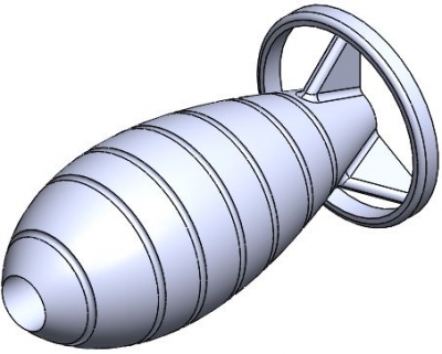
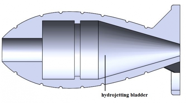
Design
The design of the combustion chamber is optimized for minimum drag through the water. We opted for a torpedo-like shape in order to achieve higher velocities at the expulsion of water.
Additionally, the chamber inflates to a spherical shape, which is advantageous, given that of all enclosed surfaces, the sphere has the largest volume to surface area ratio, thus maximizing the water expelled while minimizing the necessary material. The geometry and material selection proved to be fit, the chamber resisting to very high pressures.
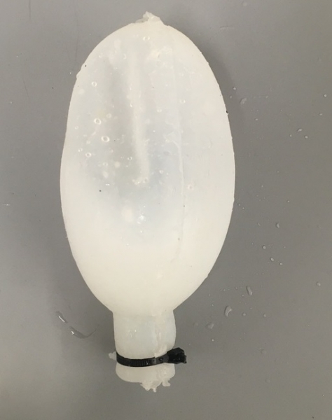
Constraint - Propelling Potential
A very important design constraint was the inflation limit of the combustion chamber, which dictates the volume of water that it can displace and thus the force generated and its potential velocity. Therefore, we tested its resistance and found a fracture point at approximately 15 N, which suffices for our purposes.

The equation for the number of moles of gas in the balloon as a function of r is given in the equation above where n is the number of moles of gas, C01 is a material constant of Ecoflex 10 Silicone given as 11.75 kPa, Vb is the initial material volume, R is the universal gas constant, T is the temperature of the gas, and r is the current radius.

Treating the Ecoflex 10 Silicone as a hyper-elastic material, a model for a balloon's volume and pressure was developed. Basic manipulation of the above equation using material properties of the silicone, electrolysis ideal energy cost, experimentally determined fuel cell efficiencies, external pressure at STP, and the displaced water volume produces a model of Buoyant Force vs Energy. Assuming a spherical elastomer with thickness of 5mm and initial radius of 5cm that weighs 0.1854Kg, the buoyant force per electrolysis energy input is as shown in the figure.

This model assumes atmospheric pressure and that energy input will increase as external pressure increases. The red circle indicates the fracture point of the material at approximately 15N.
Fabrication Overview
We used centrifugal casting to fabricate the ellipsoid expansion bladders used in the combustion and buoyancy experiments. A basic description of our manufacturing process is as follows: First spray the 3D printed ellipsoid mold with Universal® Mold Release, then mix equal parts of Ecoflex 10 part A and B and pour the mixture into our ellipsoid mold (making sure to coat the walls). Next, we place the filled mold into the rotational caster, and let it run for approximately 2 hours. After the 2 hours have passed, the mold is placed into an oven at 65 degrees Celsius for 30 minutes to ensure that the silicone inside fully cures. This general process creates a completely sealed ellipsoid expansion bladder, more detail is given in the subsequent pages.
The rotational rate of the slower rotational caster axis is 0.77 rotations per second. With an approximate 2:1 spin rate, the faster axis turns at 1.54 rotations per second. This difference in the spin rates results in an even Ecoflex coating on the interior of the ellipsoid mold, as long as the mold’s centroid is located about the center of rotation. If the mold is not centered about the center of rotation, the bladder will be misshapen. An uneven coating can also occur if the inside of both halves of the mold are not lightly brushed with Ecoflex prior to placing it in the caster. An optional additional step is turning the filled mold upside down in the rotational caster, and letting it sit for 30 seconds before starting the rotations. This may be necessary because a significant amount of time generally has elapsed between when the silicone is poured and when it is mounted in the rotational caster. The problem with that is letting the mold sit too long on one side causes the silicone to pool, which will result in a bladder with uneven walls, even after being turned by the rotational caster. There has to be a relatively even silicone distribution for the casting to work.
Bill of Materials
This page offers a detailed Bill of Materials for replicating the silicone combustion chamber.
Molds
The combustion chamber was fabricated through rotational casting, using a two part, Objet printed mold that has a sealing interface.

Molds
The Solidworks and .STL files can be downloaded from the Downloads Section.
Lab Tools


Latex Gloves Mixing Cups Tongue Depressors
Equipment


Laboratory Scale Rotational Caster


Vacuum Chamber Laboratory Oven
Materials

ECOFLEX 10
Manufacturing Process
1. Into a clean cup, pour 90 g of Ecoflex 10 part A and 90 g Ecoflex 10 part B. The final mixture should therefore weigh 180 g.

2. Using a rigid stirrer (e.g., a tongue depressor), mix the two halves together slowly, to avoid creating air bubbles. Air bubbles, when the silicone has cured, can result in rupturing at lower stresses than you would need the silicone bladder to be able to withstand during inflation.
3. To eliminate any air bubbles, put the mixing cup in a vacuum chamber. Removal of the air just above the surface of the liquid silicone in the cup will draw out any pockets of air under the surface.

4. Coat the interior of the mold halves with a mold release, then let them dry for the appropriate amount of time (generally listed on the side of the mold release can).

5. Pour half of the Ecoflex 10 mixture in each mold half, carefully coating the walls. Ecoflex 10 has a relatively low viscosity, but you should still be able to get some of it all over the interior of the mold. This will help the silicone spread once we put the filled mold on the rotational caster.
6. Carefully fit the mold halves together. While not necessary, it is generally advised that you use some kind of external binding to make sure the halves stay together.

7. Fix the mold on the rotational caster, centering it about the axis of rotation. Depending on your rotational caster, you may have to affix the mold using zip ties, bolts, etc. Your rotational caster should have an approximate 2:1 spin rate. We used 0.77 rotations per second and 1.54 rotations per second. Place the mold vertically, upside down (the bottom part is the cylindrical nozzle) in the caster for 30 seconds. This will spread the silicone.
8. Turn the mold with the nozzle facing down, and put it on the caster using the same settings.

9. Let cure for 2 hours.
10. Take the mold off the rotational caster and place it in the oven at 65 Celsius for 30 minutes.

11. Remove the mold and let it cool down.
12. Open the mold and carefully demold the silicone chamber.

Downloads
| sldprt.zip | 457 KB | |
| stl.zip | 305 KB |
Testing
A major result from our study is that electrolysis from a fuel cell consuming 1 W can produce enough fuel and oxidant for significant combustion powered hydrojetting. Furthermore, the rapid deflagration of hydrogen was capable of propelling a synthetic mantle. The figure below shows the concept for combustion powered hydrojetting in the robotic lamprey and a prototype of the hydrojetting mantle. The hydrojetting chamber is modeled after the mantle of an octopus, which squeezes water into a jet that propels it backwards. By fixing a deformable, synthetic mantle on the interior of our combustion chamber, the ignition of combustible fuel causes the mantle to deform and squeeze out water, causing propulsion.
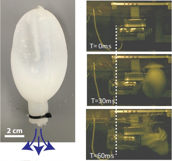
In the figure, right column shows high speed camera footage of the hydrojetting system moving at a speed of 3 m s-1, fully submerged under water. This is remarkable for many reasons, one is that the mantle was actually fixed in place to measure the force exerted. The thrust force generated was enough to dislodge it from its fixture.
Experiment Setup
The experimental setup has been designed to measure the energy input to the chamber and force output of an elastomer water jet propulsion mechanism. The energy input is measured in 3 ways. The first method is through the voltage and current input to the rover. The second is through the hydrogen gas input with volumetric flow meters. The third is gas input from the oxygen volumetric flow meters. Either volumetric flow can be used because they should be being produced in stoichiometric quantities, ensuring that each test is completely oxyhydrogen to maximize energy output.
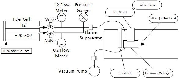
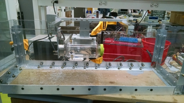
Water Jet Propulsion Force and Mobility Test Stand
Fuel cells were used to generate the hydrogen and oxygen gas for these tests. The fuel cells used were Horizon Technology PEM Fuel Cells meant for educational demonstrations and cost less than $50. The electrical energy input to the fuel cells was indirectly measured through voltage and current through known loads. Additionally, two pressure based flow meters were used to measure the standard cubic centimeters of hydrogen and oxygen produced. A pressure gauge was placed in series and is used to determine when a pressure equilibrium is reached between the inside of the elastomer waterjet and the atmosphere. A load cell is used to determine the propulsive force generated by the the waterjet. Finally, a high speed camera captures the dynamics of the waterjetting process and is capable of indicating everything from the volumetric expansion rate of the gas, strain rate of the elastomer, and velocity of the combustion chamber.
The process for measuring the force output by the elastomer hydrojet and energy input is as follows:
- A vacuum pump is used to remove a majority of the gas from the chamber typically down to -0.7psi. This removes the gasses contained in the hoses and elastomer waterjet which contain a combination of oxygen, hydrogen, water vapor, water, nitrogen, and the other trace elements that constitute air. This is not sufficient to pull a complete vacuum, but removes some of the remnant gasses.
- The fuel cells are powered until they have produced the desired volume of gas
- The voltage applied to the fuel cells is measured
- The voltage drop across a known resistance in series with the fuel cells is measured
- The power to the fuel cells are turned off
- The Hydrogen gas and Oxygen gas supply valves are closed
- The gas supply data is saved
- The load cell data collection is turned on
- The Glow Plug ignition switch current limiter is removed
- The high speed camera begins recording
- The gas is ignited
- The high speed camera recording is saved
- The load cell data is saved
Occasionally, the gas does not initially ignite and a second recording must occur.
After the first combustion of the day, the following anomalies tend to occur that change the dynamics of the test. The gas in the chamber has lots of condensation and water vapor from the previous combustion that adds to the residual gasses in the test. This may contribute to subsequent tests occurring at lower expansion times than the first test. The glow plug is also often coated in water. In order for the H2 and O2 gas to combust, the glow plug must run long enough for the water droplets condensed on the surface of the glowplug to evaporate and the local concentration of H2 and O2 to reach the minimum ignition concentration.
The load cell data is limited in rise time and peak time by the amplifier used.
Experimental Results
Unconstrained Hydrojet Powered Mantle Motion
In order to determine a rough order of magnitude of the velocity a hydrojetting mechanism could achieve, the test setup was modified by removing the load cell. Using the high speed camera, frame by frame motion of the mantle was recorded and can be observed in the figure below. From this high speed imagery, velocimetry can be performed to determine the velocity of the mantle. The maximum velocity of the mantle and bladder is 200 in s-1 or 0.5 m s-1 . It should be noted that this bladder burst during the test as the high velocity mantle pulled the thin walled silicone bladder into the sharp edge of the test stand holding it in place. Careful observation of the T=20 ms frame shows the bladder’s contact with the test stand. Based on the propagation of gas in T=40ms, it is clear that this was the cause of the failure.
The flow meters indicate a hydrogen gas input of 189.69 scc(standard cubic centimeters) at STP. Using the ideal gas law, the total number of moles of hydrogen gas is estimated to be 0.0078 moles. Using the same method on the oxygen flow meter resulted in the expected 0.0039 moles, exactly half that of the hydrogen gas. By back calculating the number of moles of gas and using 80% efficiency of our fuel cells, the energy input to the system is 3.54 kJ. Running this combustion in Europa’s ocean will take slightly less than 1 hour with a 1 watt electrodynamic tether.
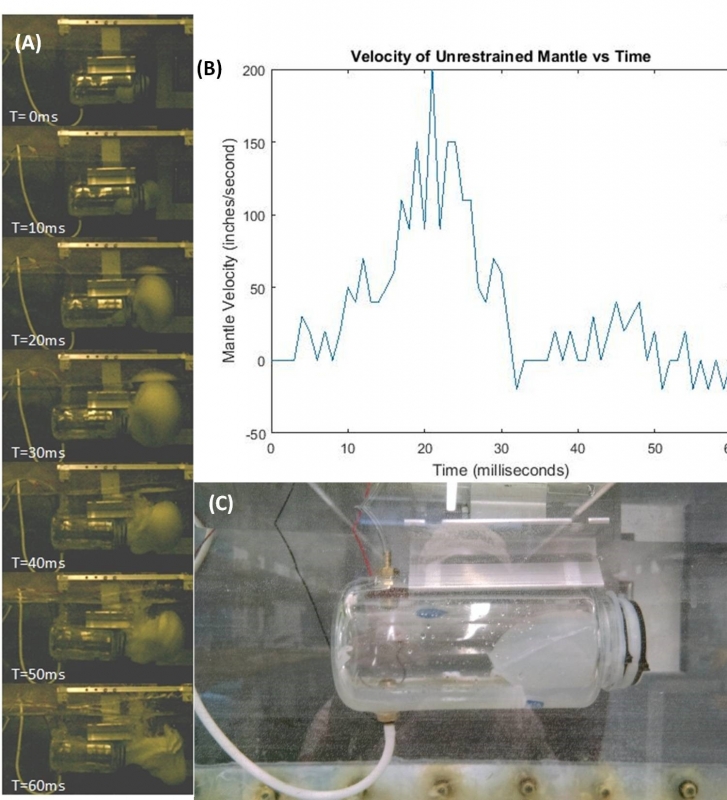
It is worth noting that the bladder inside the mantle as indicated in Figure (c) is approximately 4 inches long initially and cylindrical in shape with 0.3175 cm wall thickness. As Figure (c) shows, the bladder is not in a cylindrical shape at the beginning of the test due to acting of the water on the bladder. This indicates that even the small pressure difference between the bottom and top of the mantle, a 5 cm height difference, causes an uneven expansion of the bladder. This expansion of the bladder could be caused by three different sources (i) initial alignment of the bladder due to gravity acting on the higher density water that vectors expansion upwards (ii) buoyant forces acting on the bladder during the gas expansion phase of combustion resulting in upward motion and/or (iii) the local high pressures in the water tank experimental setup.