Design Overview
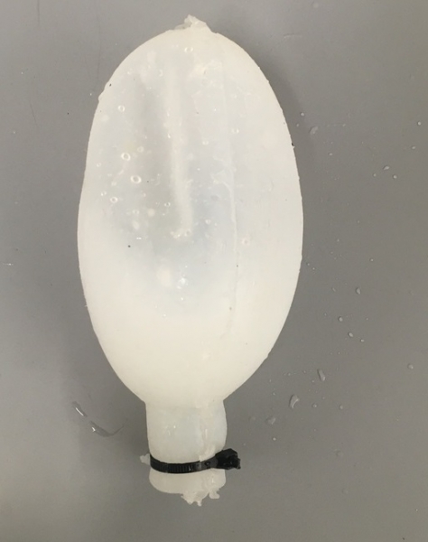
Our underwater combustion system mimics the behavior of cephalopods (e.g., octopuses, squids and cuttlefish). They escape threatening situations by quickly inflating a mantle and expelling fluid, propelling them several body lengths forward. This rapid shape-shift allows them to overcome effects of flow-separation and cavitation formation. We aim to mimic this behavior by designing and building a similar silicone combustion bladders and chamber.


Design
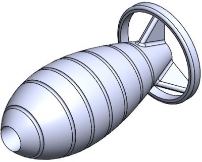
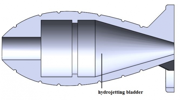
The design of the combustion chamber is optimized for minimum drag through the water. We opted for a torpedo-like shape in order to achieve higher velocities at the expulsion of water.
Additionally, the chamber inflates to a spherical shape, which is advantageous, given that of all enclosed surfaces, the sphere has the largest volume to surface area ratio, thus maximizing the water expelled while minimizing the necessary material. The geometry and material selection proved to be fit, the chamber resisting to very high pressures.

Constraint - Propelling Potential
A very important design constraint was the inflation limit of the combustion chamber, which dictates the volume of water that it can displace and thus the force generated and its potential velocity. Therefore, we tested its resistance and found a fracture point at approximately 15 N, which suffices for our purposes.

The equation for the number of moles of gas in the balloon as a function of r is given in the equation above where n is the number of moles of gas, C01 is a material constant of Ecoflex 10 Silicone given as 11.75 kPa, Vb is the initial material volume, R is the universal gas constant, T is the temperature of the gas, and r is the current radius.

Treating the Ecoflex 10 Silicone as a hyper-elastic material, a model for a balloon's volume and pressure was developed. Basic manipulation of the above equation using material properties of the silicone, electrolysis ideal energy cost, experimentally determined fuel cell efficiencies, external pressure at STP, and the displaced water volume produces a model of Buoyant Force vs Energy. Assuming a spherical elastomer with thickness of 5mm and initial radius of 5cm that weighs 0.1854Kg, the buoyant force per electrolysis energy input is as shown in the figure.

This model assumes atmospheric pressure and that energy input will increase as external pressure increases. The red circle indicates the fracture point of the material at approximately 15N.