Testing
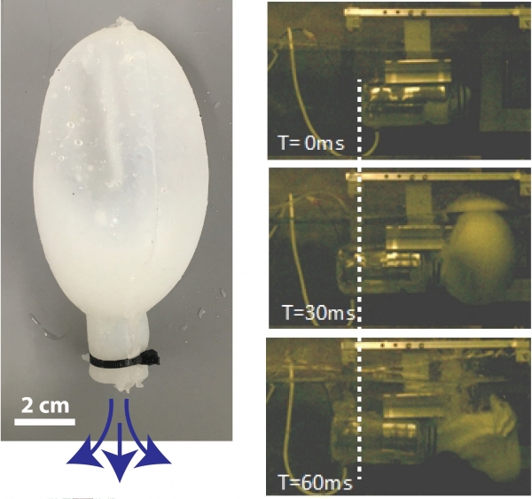
A major result from our study is that electrolysis from a fuel cell consuming 1 W can produce enough fuel and oxidant for significant combustion powered hydrojetting. Furthermore, the rapid deflagration of hydrogen was capable of propelling a synthetic mantle. The figure below shows the concept for combustion powered hydrojetting in the robotic lamprey and a prototype of the hydrojetting mantle. The hydrojetting chamber is modeled after the mantle of an octopus, which squeezes water into a jet that propels it backwards. By fixing a deformable, synthetic mantle on the interior of our combustion chamber, the ignition of combustible fuel causes the mantle to deform and squeeze out water, causing propulsion.

In the figure, right column shows high speed camera footage of the hydrojetting system moving at a speed of 3 m s-1, fully submerged under water. This is remarkable for many reasons, one is that the mantle was actually fixed in place to measure the force exerted. The thrust force generated was enough to dislodge it from its fixture.
Experiment Setup
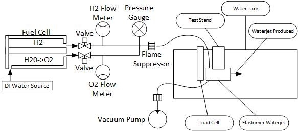
The experimental setup has been designed to measure the energy input to the chamber and force output of an elastomer water jet propulsion mechanism. The energy input is measured in 3 ways. The first method is through the voltage and current input to the rover. The second is through the hydrogen gas input with volumetric flow meters. The third is gas input from the oxygen volumetric flow meters. Either volumetric flow can be used because they should be being produced in stoichiometric quantities, ensuring that each test is completely oxyhydrogen to maximize energy output.

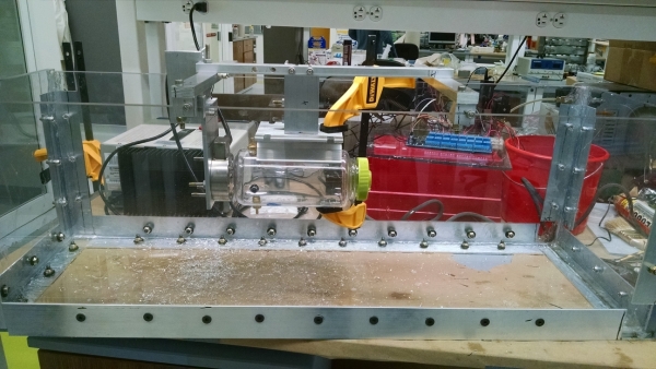
Water Jet Propulsion Force and Mobility Test Stand
Fuel cells were used to generate the hydrogen and oxygen gas for these tests. The fuel cells used were Horizon Technology PEM Fuel Cells meant for educational demonstrations and cost less than $50. The electrical energy input to the fuel cells was indirectly measured through voltage and current through known loads. Additionally, two pressure based flow meters were used to measure the standard cubic centimeters of hydrogen and oxygen produced. A pressure gauge was placed in series and is used to determine when a pressure equilibrium is reached between the inside of the elastomer waterjet and the atmosphere. A load cell is used to determine the propulsive force generated by the the waterjet. Finally, a high speed camera captures the dynamics of the waterjetting process and is capable of indicating everything from the volumetric expansion rate of the gas, strain rate of the elastomer, and velocity of the combustion chamber.
The process for measuring the force output by the elastomer hydrojet and energy input is as follows:
- A vacuum pump is used to remove a majority of the gas from the chamber typically down to -0.7psi. This removes the gasses contained in the hoses and elastomer waterjet which contain a combination of oxygen, hydrogen, water vapor, water, nitrogen, and the other trace elements that constitute air. This is not sufficient to pull a complete vacuum, but removes some of the remnant gasses.
- The fuel cells are powered until they have produced the desired volume of gas
- The voltage applied to the fuel cells is measured
- The voltage drop across a known resistance in series with the fuel cells is measured
- The power to the fuel cells are turned off
- The Hydrogen gas and Oxygen gas supply valves are closed
- The gas supply data is saved
- The load cell data collection is turned on
- The Glow Plug ignition switch current limiter is removed
- The high speed camera begins recording
- The gas is ignited
- The high speed camera recording is saved
- The load cell data is saved

Occasionally, the gas does not initially ignite and a second recording must occur.
After the first combustion of the day, the following anomalies tend to occur that change the dynamics of the test. The gas in the chamber has lots of condensation and water vapor from the previous combustion that adds to the residual gasses in the test. This may contribute to subsequent tests occurring at lower expansion times than the first test. The glow plug is also often coated in water. In order for the H2 and O2 gas to combust, the glow plug must run long enough for the water droplets condensed on the surface of the glowplug to evaporate and the local concentration of H2 and O2 to reach the minimum ignition concentration.
The load cell data is limited in rise time and peak time by the amplifier used.
Experimental Results
Unconstrained Hydrojet Powered Mantle Motion
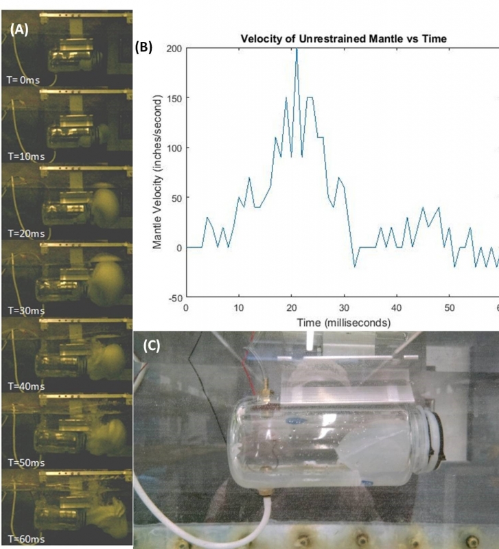
In order to determine a rough order of magnitude of the velocity a hydrojetting mechanism could achieve, the test setup was modified by removing the load cell. Using the high speed camera, frame by frame motion of the mantle was recorded and can be observed in the figure below. From this high speed imagery, velocimetry can be performed to determine the velocity of the mantle. The maximum velocity of the mantle and bladder is 200 in s-1 or 0.5 m s-1 . It should be noted that this bladder burst during the test as the high velocity mantle pulled the thin walled silicone bladder into the sharp edge of the test stand holding it in place. Careful observation of the T=20 ms frame shows the bladder’s contact with the test stand. Based on the propagation of gas in T=40ms, it is clear that this was the cause of the failure.
The flow meters indicate a hydrogen gas input of 189.69 scc(standard cubic centimeters) at STP. Using the ideal gas law, the total number of moles of hydrogen gas is estimated to be 0.0078 moles. Using the same method on the oxygen flow meter resulted in the expected 0.0039 moles, exactly half that of the hydrogen gas. By back calculating the number of moles of gas and using 80% efficiency of our fuel cells, the energy input to the system is 3.54 kJ. Running this combustion in Europa’s ocean will take slightly less than 1 hour with a 1 watt electrodynamic tether.

It is worth noting that the bladder inside the mantle as indicated in Figure (c) is approximately 4 inches long initially and cylindrical in shape with 0.3175 cm wall thickness. As Figure (c) shows, the bladder is not in a cylindrical shape at the beginning of the test due to acting of the water on the bladder. This indicates that even the small pressure difference between the bottom and top of the mantle, a 5 cm height difference, causes an uneven expansion of the bladder. This expansion of the bladder could be caused by three different sources (i) initial alignment of the bladder due to gravity acting on the higher density water that vectors expansion upwards (ii) buoyant forces acting on the bladder during the gas expansion phase of combustion resulting in upward motion and/or (iii) the local high pressures in the water tank experimental setup.