Pneumatic Deformation Sensors
Pneumatic Deformation Sensors (PDS's) are a new type of soft sensor designed for use with soft robots. The sensors are intended to provide feedback on how they deform, hence them being deformation sensors. They can be fitted and utilized in many soft robotic actuators, such as the actuators on the Soft Robotics Toolkit.
The Background section will discuss the need for feedback sensors and how Pneumatic Deformation Sensors work.
The Design section will go over the specifics of a PDS, including a diagram and how to design a PDS for a soft robot or soft robotic actuator.
The Fabrication section will instruct how to build the basic pre-designed version of a PDS. This includes a Bill of Materials, a list of needed tools, and a step-by-step instructions for the building of the sensor and the assembly of the electronics with detailed pictures.
The Testing section will analyze the effectiveness of PDS's, with included graphs and data tables.
Background
Pneumatic Deformation Sensors were developed as a solution for simple sensing ability and providing precise feedback of soft robotic actuators. Many soft actuators suffer from being very inaccurate and difficult for use in precision-based tasks. Hard robotics actuators experience this to a tremendously lesser degree, as they typically have some form of sensor-based feedback. For example, servo motors are DC motors with an attached potentiometer. The feedback from this sensor allows for consistent rotation and movement with a high-degree of precision. If soft robotic actuators had similar methods of feedback, they could have much more complex motion. Unfortunately, the sensors used for feedback in hard robots (potentiometers, encoders, etc.) are hard and would compromise the "soft" qualities of a soft robot. As a result, soft sensors must be developed in order to have sensors that can provide feedback for soft robots. This is where Pneumatic Deformation Sensors come into play. PDS's can be made from soft materials, such as low-durometer silicones, air-tight fabrics, and more. PDS's are also very simple to implement in existing soft robot designs. The Design section goes into more detail about this.
Design
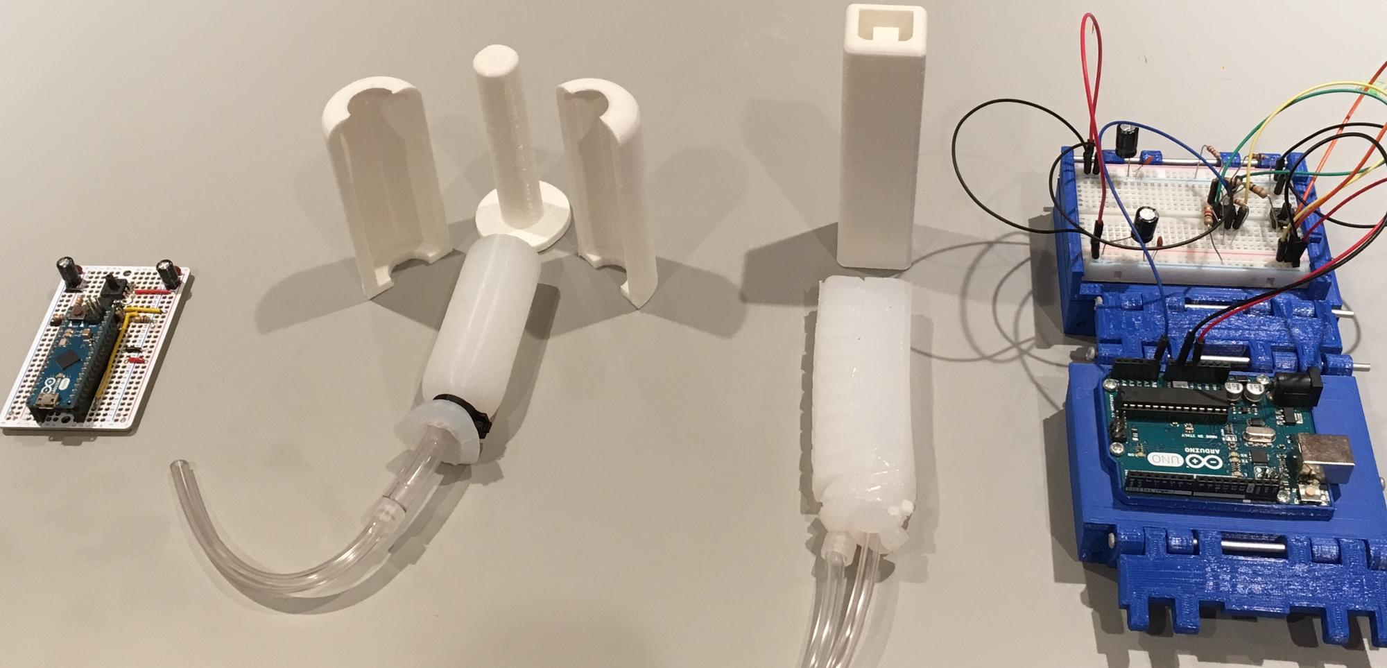
Simply put, a Pneumatic Deformation Sensor is a soft air bladder connected to an electrical pressure sensor. When the bladder deforms, whether it is being compressed, twisted or stretched, the air inside changes in pressure. This change in pressure can then be read by a pressure sensor and a microcontroller.
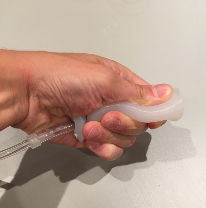
There are two designs available in this guide for PDS's. The first one is meant to demonstrate the concept and is meant to be squeezed and pulled. The second design is meant to show an application of PDS's and is a sensor attached to an existing soft robotic actuator.
Although any soft, airtight structure can be used as a PDS, certain geometries and specifications will function better than others. This is covered in-depth in the Sensor Design Guide.
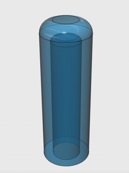
The air bladder itself can be made from a variety of soft materials. Both of the designs shown use low-durometer silicones casted in 3D printed molds, however, there is nothing to prevent other soft and airtight materials from being used, such as airtight fabric or plastic.
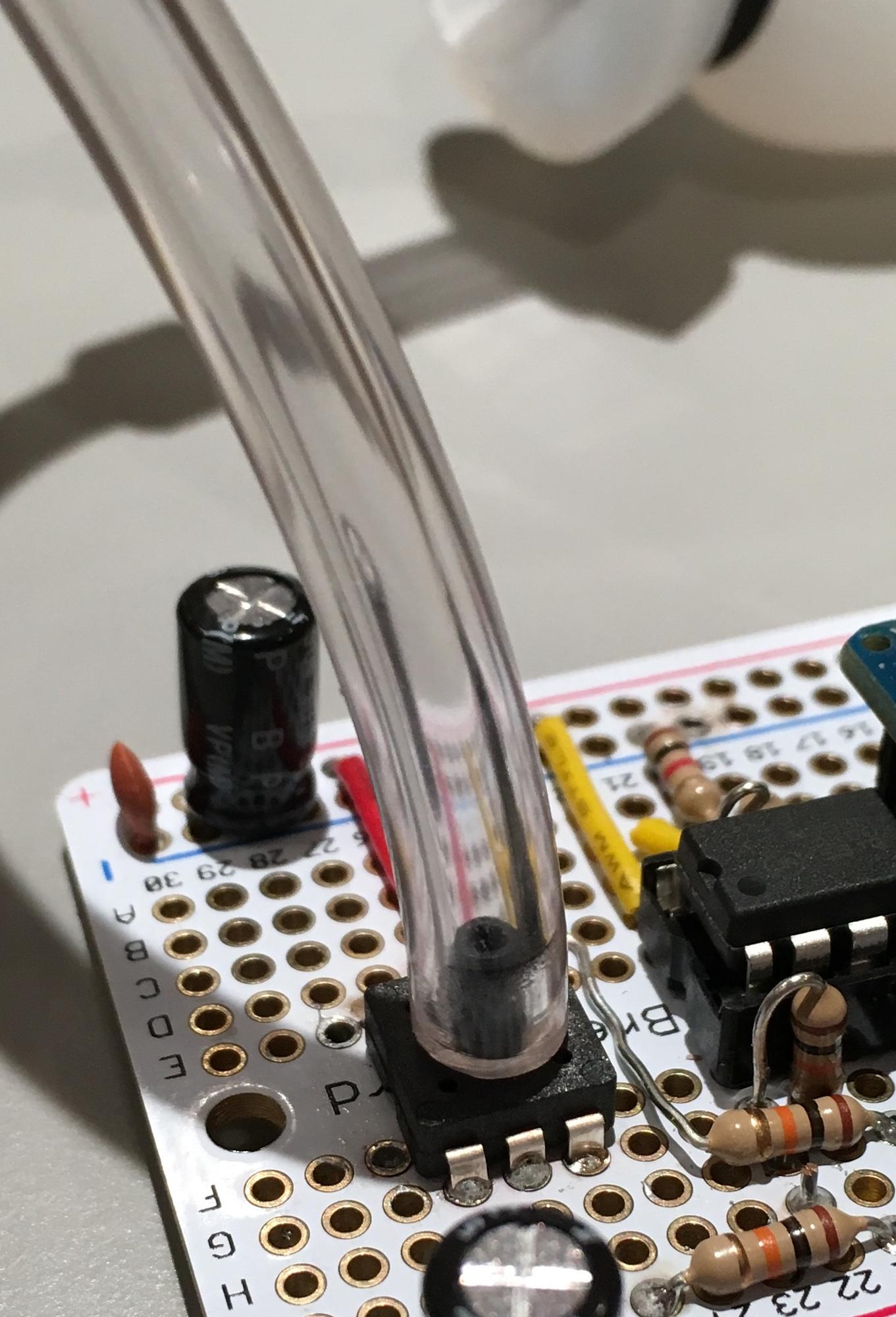
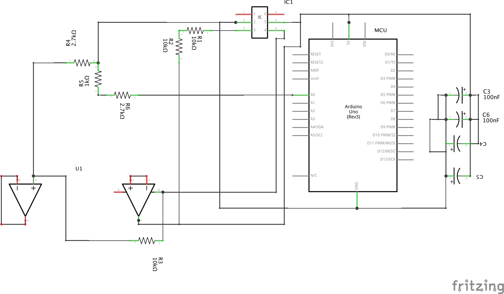
The circuitry shown in this guide is based on the MPS20N0040D-D Pneumatic pressure sensor and needs an Op-Amp to amplify the signal and an Arduino microcontroller to read it. There are two circuits shown, one for a breadboard and one for a perfboard with soldered components.
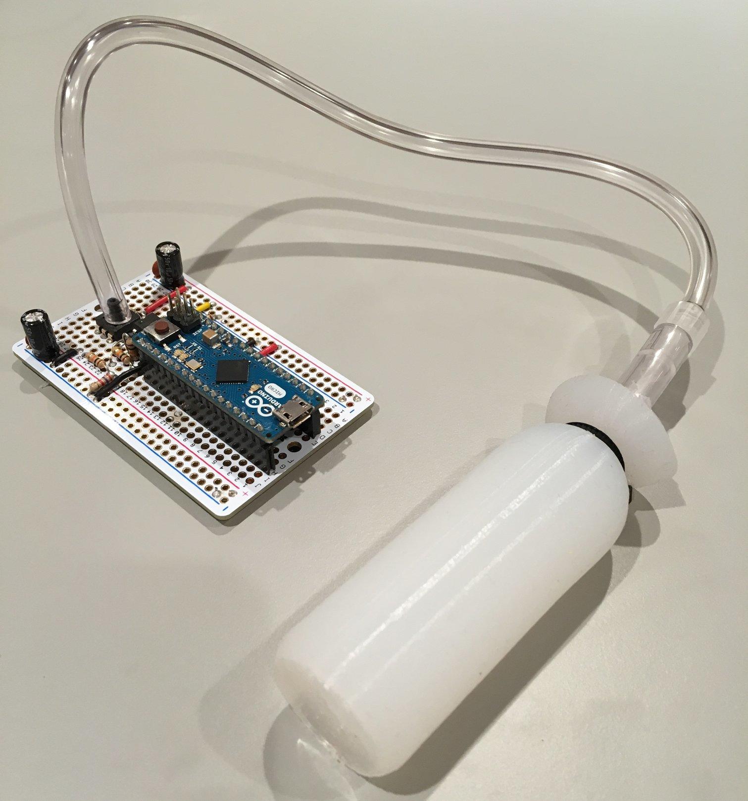
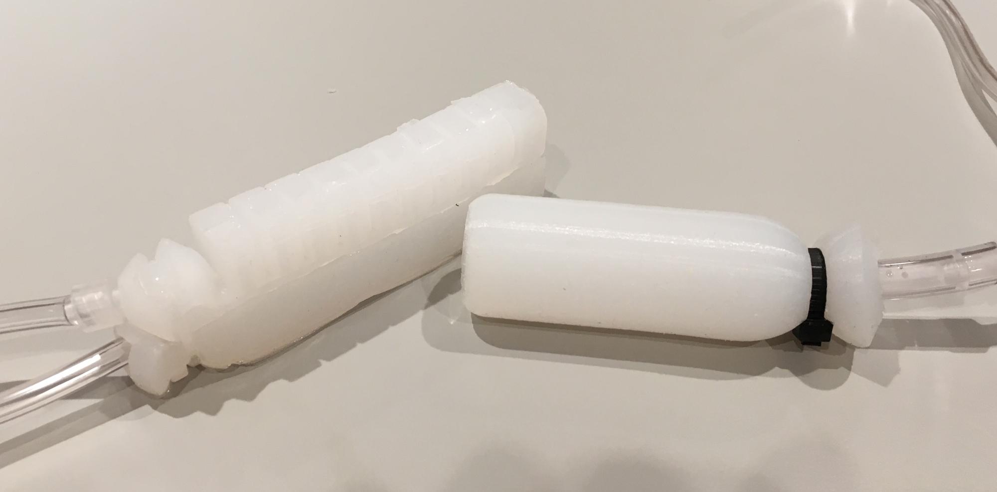
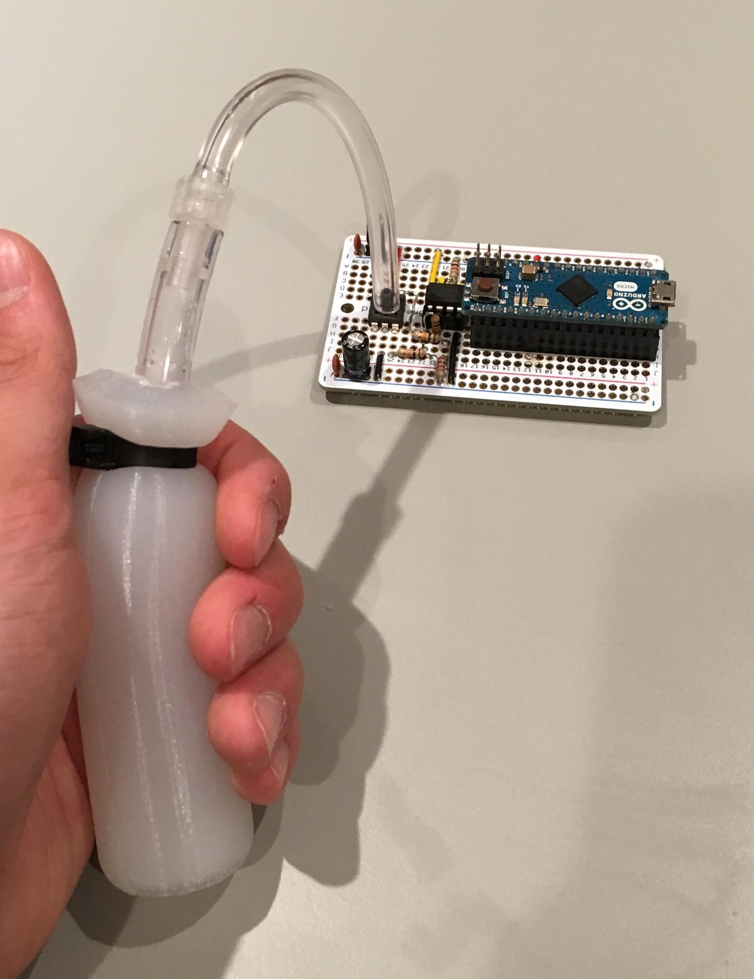
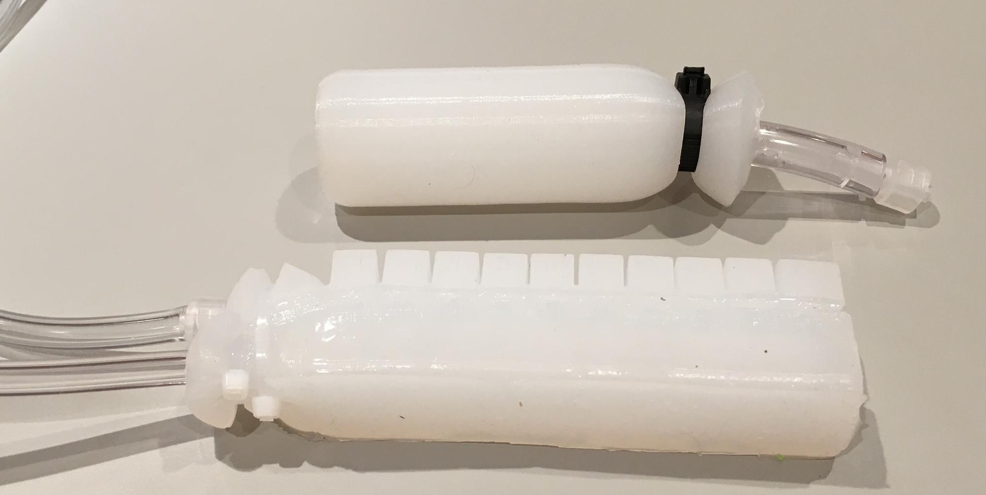
Design 1
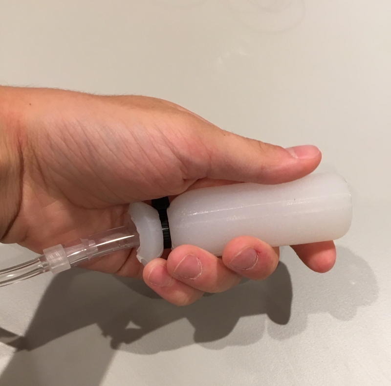
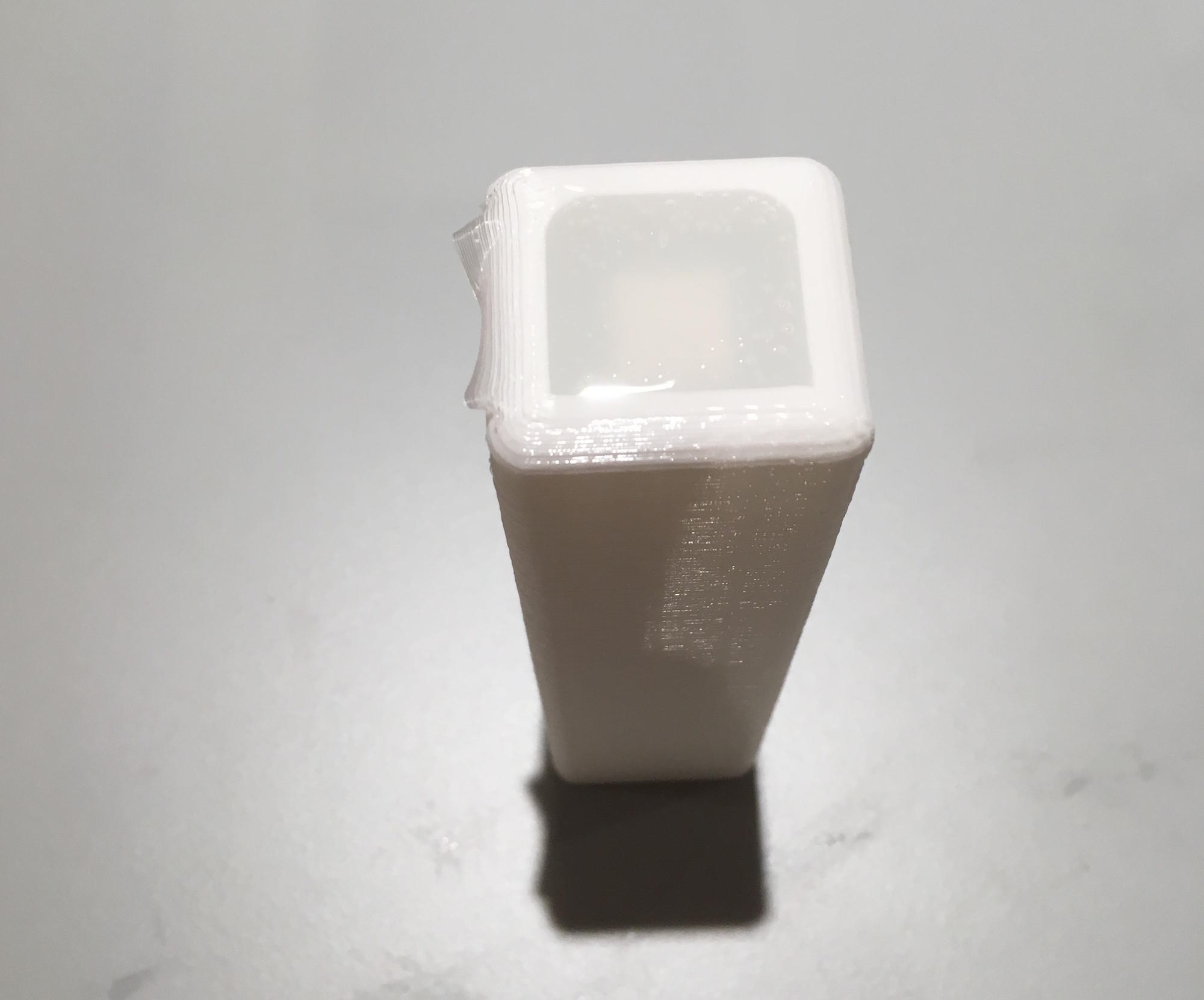
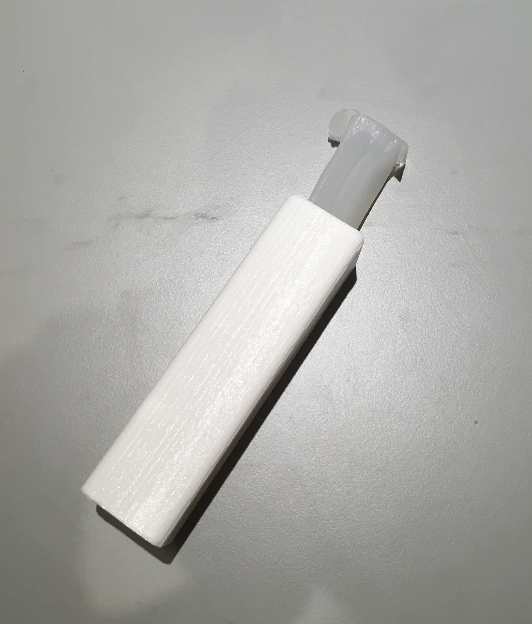
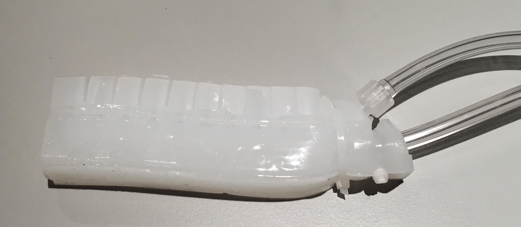
This design is meant to simply demonstrate Pneumatic Deformation Sensors and is designed to be an independent sensor. When the sensor is squeezed, its internal pressure increases to a maximum of 10 PSI. It consists of Ecoflex 00-30 silicone with an internal cavity of 21.5cm3 and a wall thickness of 6mm. The .STLs for the three-part mold are on the Downloads page and the Bill of Materials and the instructions for building can be found on the Fabrication page.
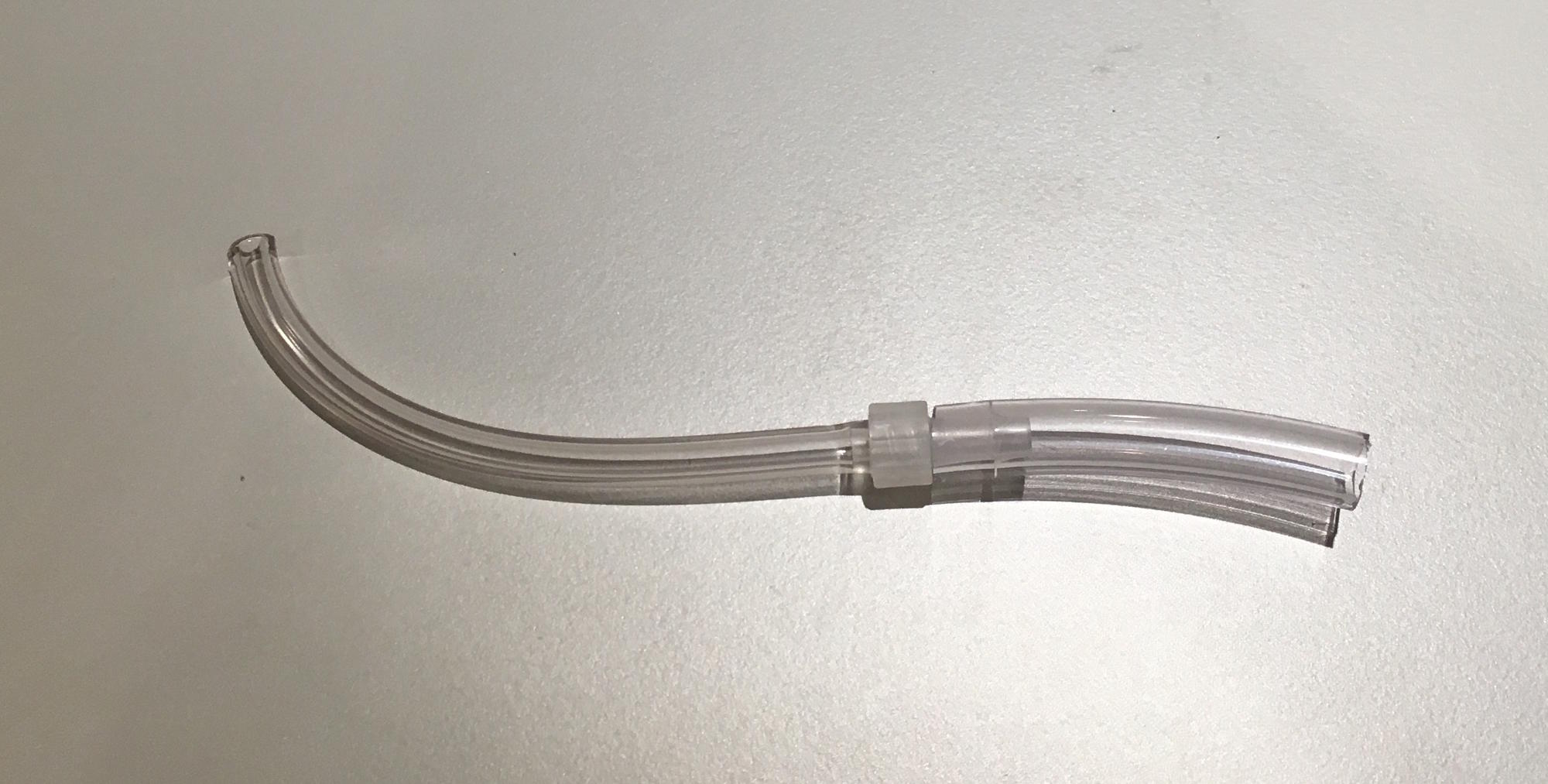
Design 2
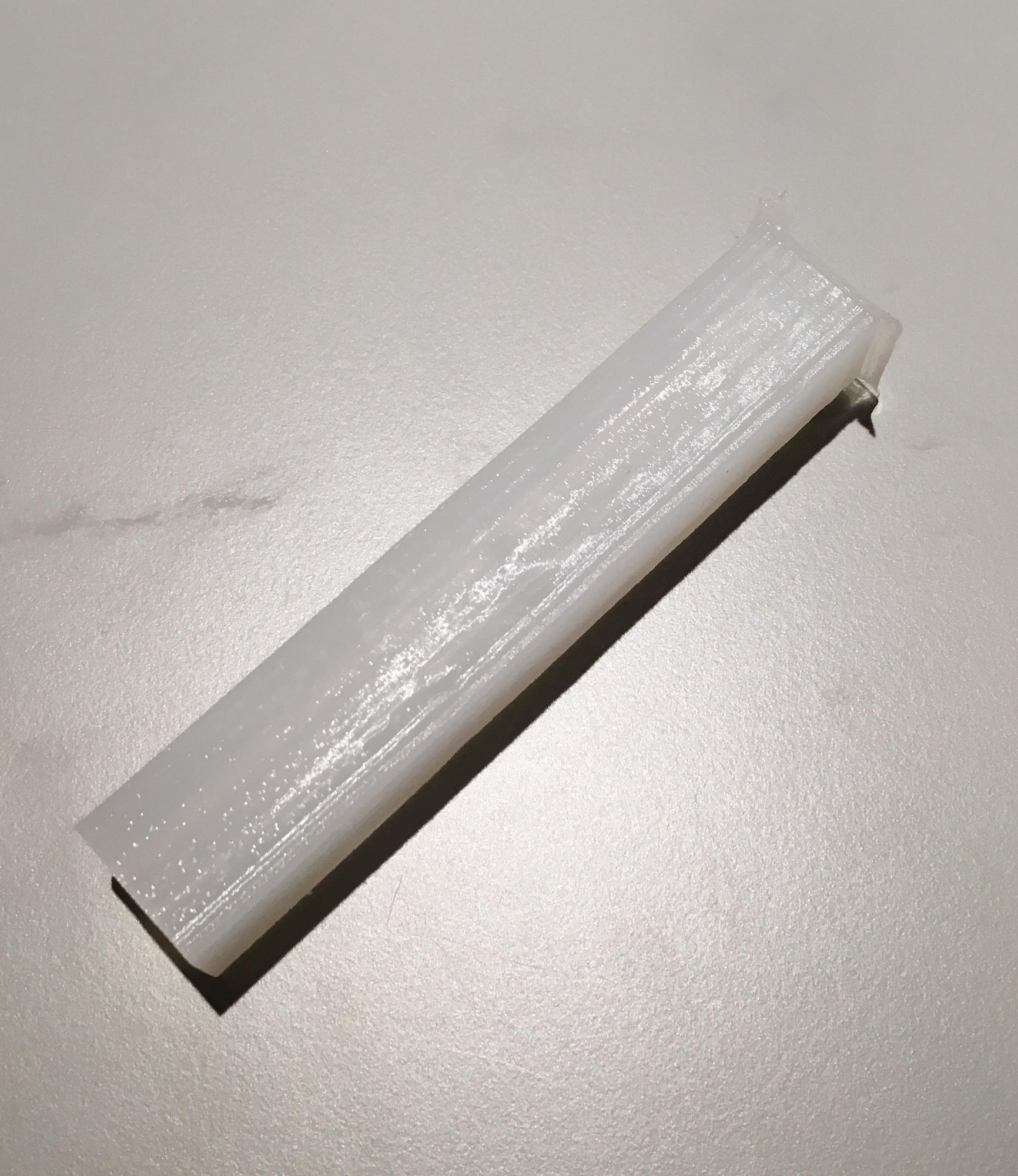
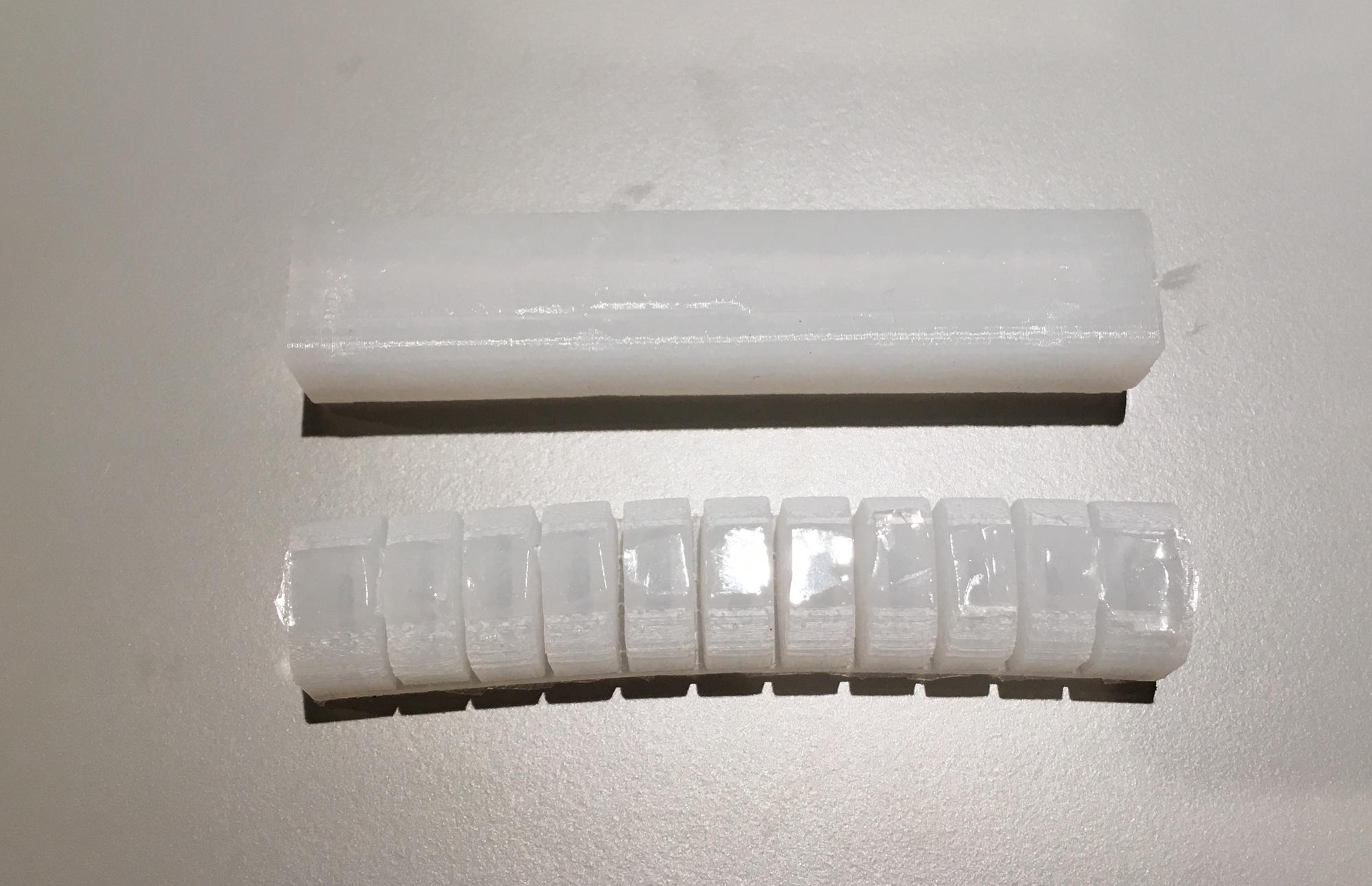
This design is meant to show a use-case for Pneumatic Deformation Sensors. It consists of an Ecoflex 00-30 PDS attached to a PneuNets Bending Actuator. When the actuator is inflated, the sensor is bent, causing its internal pressure to increase up to 2 PSI. The sensor itself has an internal volume of 8.2cm3. The .STL for the mold are on the Downloads page and the Bill of Materials and the instructions for building can be found on the Fabrication page.
Sensor Design Guide
When designing a Pneumatic Deformation Sensor, it is useful to use Boyle's Law. Boyle's Law states that volume and pressure are inversely related. It's equation is P1V1 = P2V2, where P1 and V1 are the initial pressure and volume and P2 and V2 are final pressure and volume. In a PDS, P1 is ~15 PSI, as that is atmospheric temperature (the PDS code subtracts this). V1 is the volume of the internal chamber of the PDS when not deformed. In Design 1, this is 21.5cm3. In order to figure out the pressure that the sensor will output when deformed, the volume of the sensor when deformed is needed. This is difficult to quantitatively measure and will depend on the type of deformation that the sensor is sensing.For example, a sensor designed to sense bending will deform less than one that is designed to sense compression. When compressed by hand, Design 1's volume decreases to ~13cm3. If the values that are known are substituted into the equation, the value of P2 can be found to be ~25 PSI. With the atmospheric pressure (~15 PSI) subtracted, 10 PSI can be seen as the maximum pressure that the sensor will output. This can be reversely used to design a PDS that will give a desired pressure output. For example, a sensor with an output pressure of 5 PSI can consist of a volume of 15cm3 if it's minimum deformed volume is ~11cm3.
In order for a sensor to provide feedback for a soft robotic actuator, it must be designed so that the actuator deforms the sensor when actuated. In the case of Design 2, the PneuNets Bending Actuator bends, compressing the sensor beneath it.
Electronics
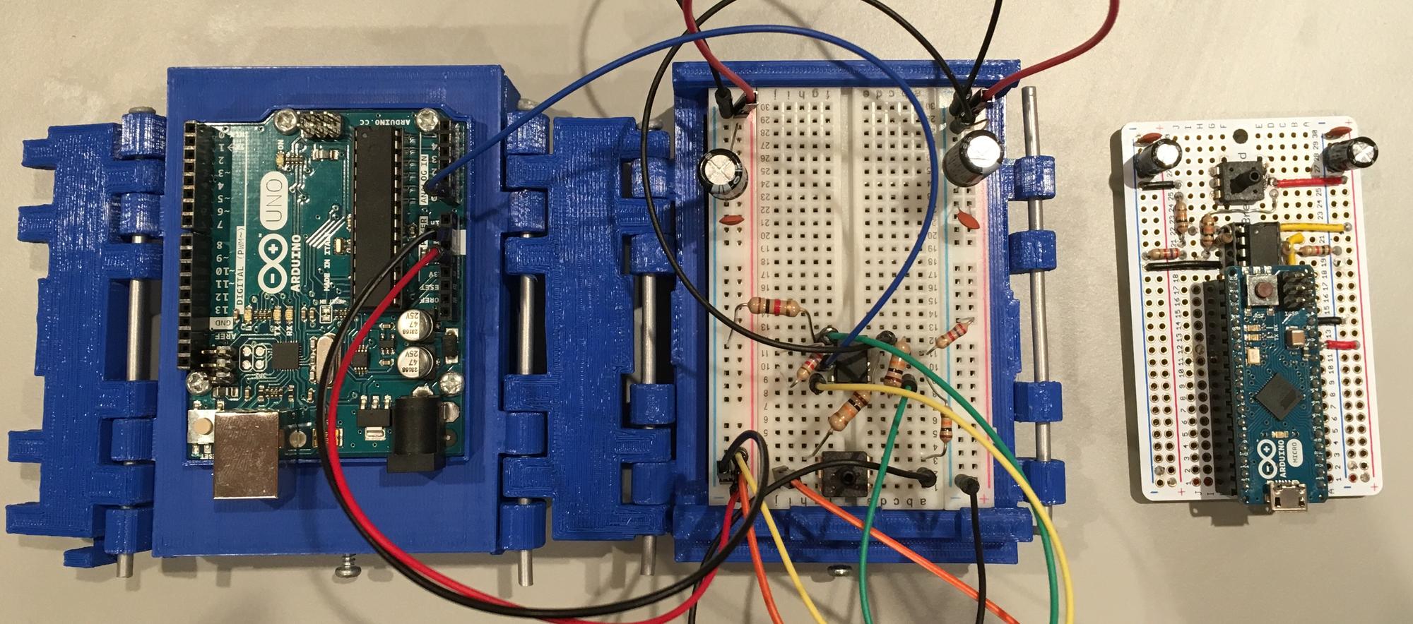
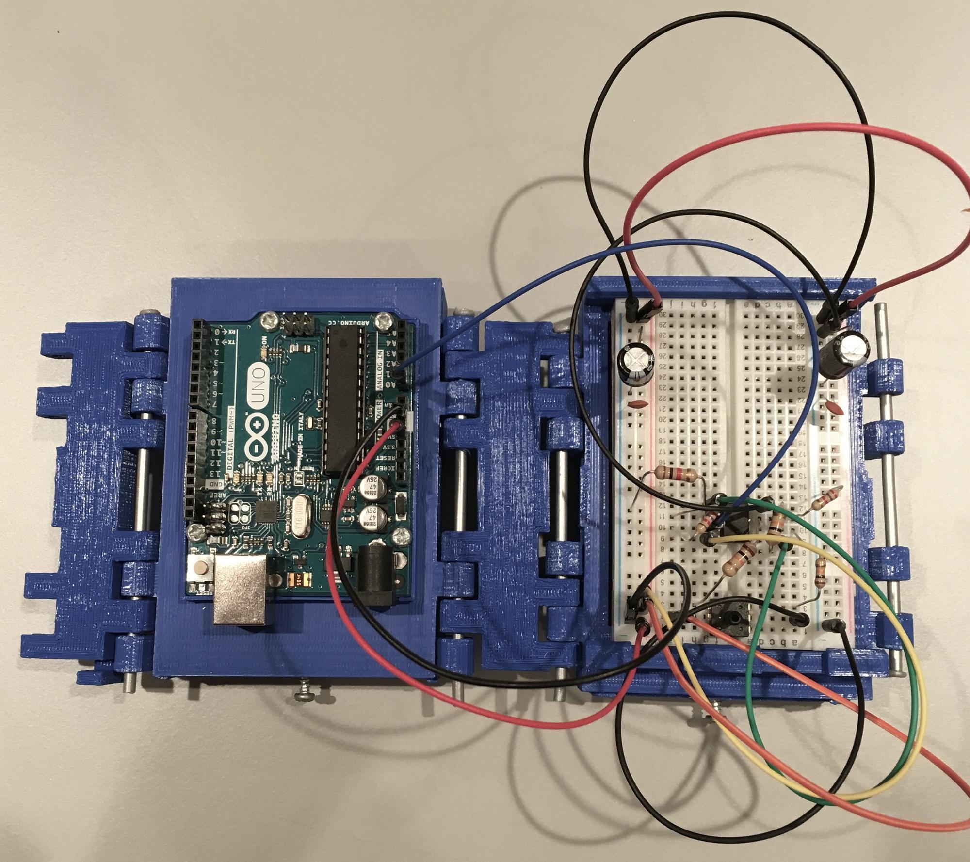
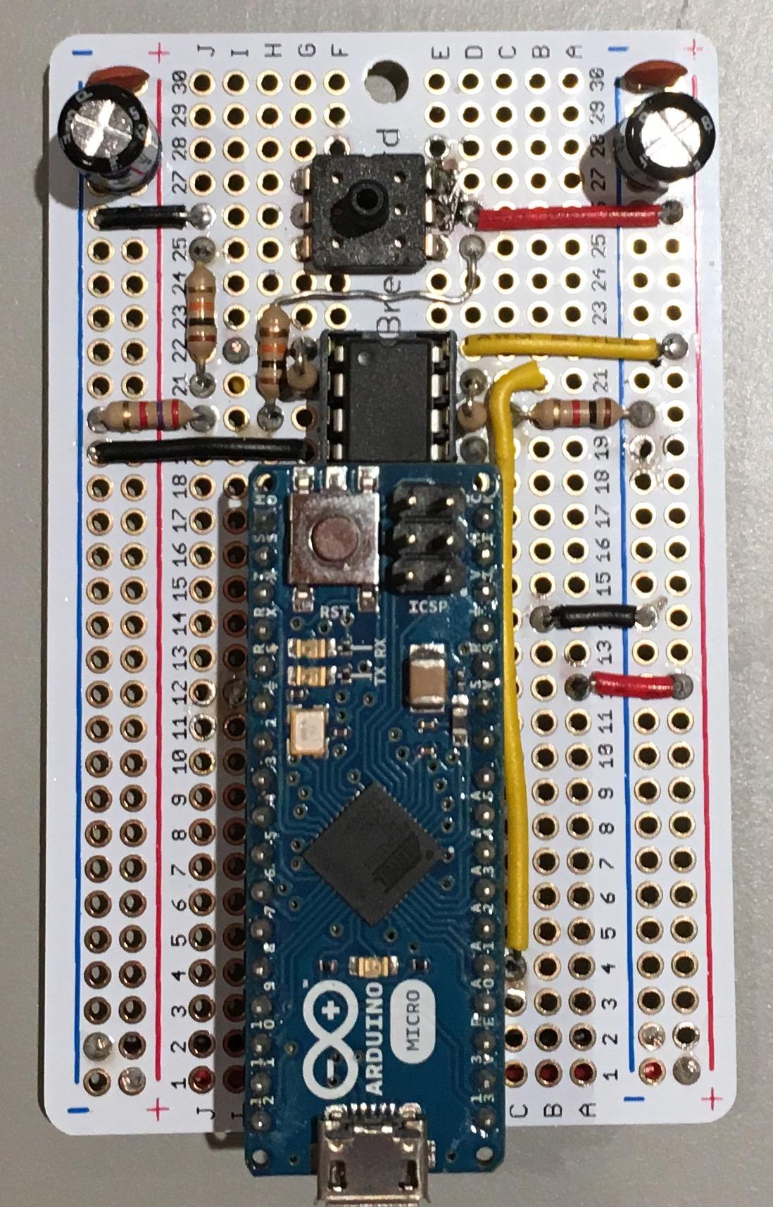
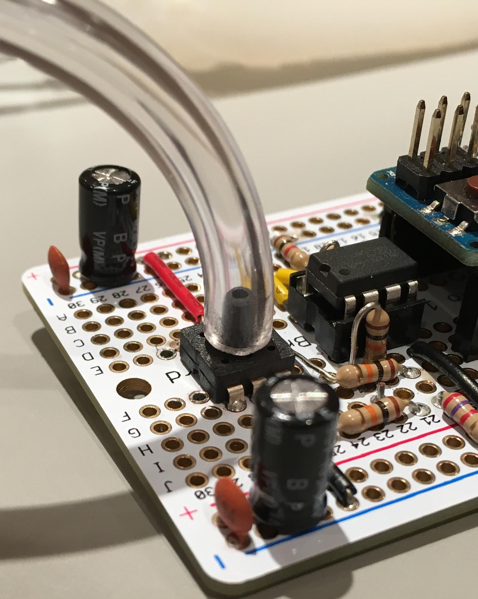
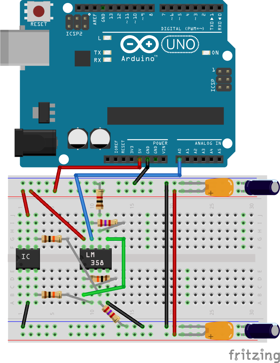
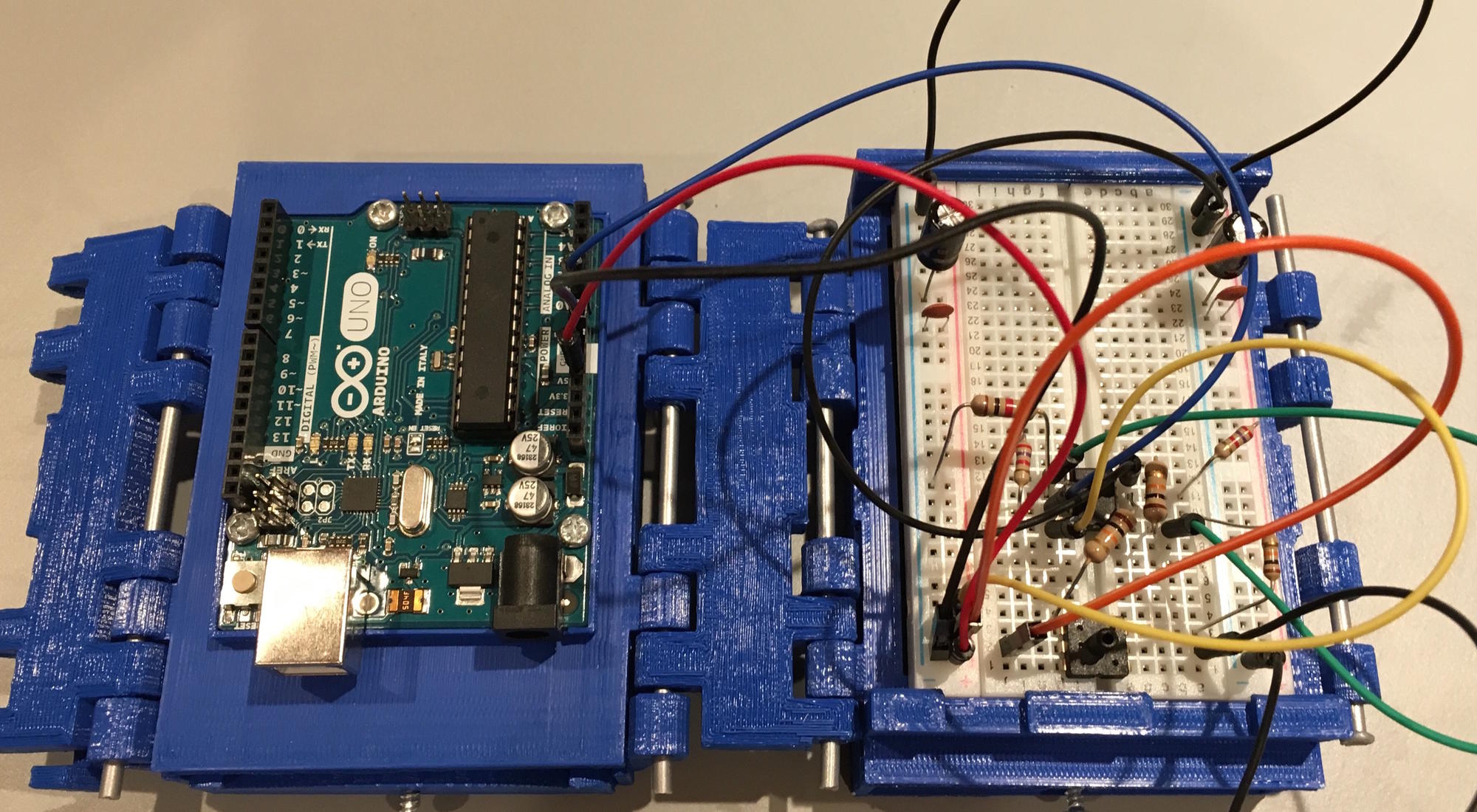
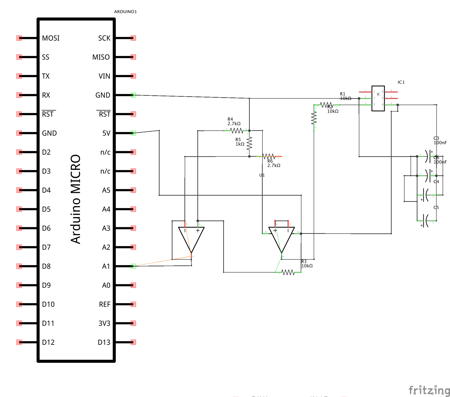
The electronics for a Pneumatic Deformation Sensor consists of the MPS20N0040D-D pressure sensor, the LM358 dual Op-Amp, and an Arduino microcontroller. There are two versions of the electronics, a version built on a breadboard with an Arduino Uno, and a version that is soldered to a perfboard with an Arduino Micro. The breadboard version is easier and quicker to build while the soldered version takes longer, requires more electronics skills, but is recommended for doing any serious work with PDS's. Both versions can be powered via USB. The diagrams and schematics for both systems along with the datasheets for the MPS20N0040D-D and the LM358 can be found on the Downloads page. The Bill of Materials and instructions for both versions can be found in the Fabrication section.
NOTE: The breadboard version of the electronics in this guide is shown with the Arduino and the breadboard attached via a case. This is not required.
Fabrication
This section will discuss what is needed and how to build both Pneumatic Deformation Sensors. The following page has a bill of materials for sensor designs 1 and 2 and both breadboard and soldered versions of the circuit. The pages after that has step-by-step instructions for building all of the previously mentioned things.
The instructions for the circuits will require knowledge of reading a circuit diagrams and soldering skills. Tutorials for said things can be found here and here.
Bill of Materials
Design 1 Bill of Materials
Materials:
| Name | Quantity | Picture | Link | Notes |
| Ecoflex 00-30 Silicone | 1 | 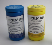 | Via Amazon | |
| Zip-Tie | 1 | 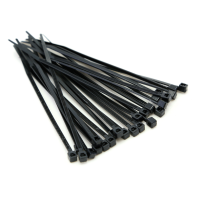 | Via Amazon | |
| 1/8" Tubing | at least 2" | 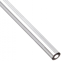 | Via Amazon | |
| 1/4" Tubing | at least 1" | 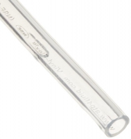 | Via Amazon | |
| Filament | at least 350g | 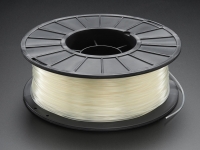 | Via Adafruit | Will depend on your printer |
| Luer Fitting | 1 | 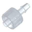 | Via Cole Parmer |
Tools:
| Name | Notes |
| 3D Printer | Must have a z-axis of at least 100mm |
| Clamps | |
| Cup | |
| Spoon | |
| Scoop | |
| Screwdriver | |
| Flush Snips |
Design 2 Bill of Materials
Materials:
| Name | Quantity | Picture | Link | Notes |
| Ecoflex 00-30 Silicone | 1 | | Via Amazon | |
| Zip-Tie | 2 | | Via Amazon | |
| Filament | at least 150g | | Via Adafruit | Will depend on your printer |
| 1/8" Tubing | 2 lengths of at least 3" | | Via Amazon | |
| Luer Fitting | 1 | | Via Cole Parmer |
Tools:
| Name | Notes |
| 3D Printer | Must have a z-axis of at least 100mm |
| Clamp | |
| Cup | |
| Spoon | |
| Scoop | |
| Flush Snips | |
| Syringe | An air compressor or squeeze bulb could be used too |
Electronics (Breadboard)
Materials:
| Name | Quantity | Picture | Link | Notes |
| Arduino Uno | 1 | 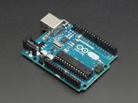 | Via Adafruit | An Arduino Leonardo could also be used here |
| Half-Sized Breadboard | 1 | 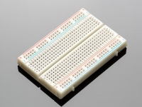 | Via Adafruit | |
| 10KΩ Resistor | 3 | 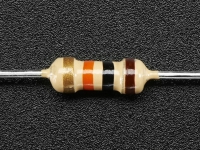 | Via Adafruit | |
| 2.7KΩ Resistor | 2 | 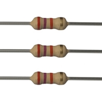 | Via Amazon | |
| 1KΩ Resistor | 1 | 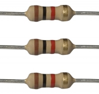 | Via Amazon | |
| 0.1uF Capacitor | 2 |  | Via Amazon | |
| 10uF 50v Electrolytic Capacitor | 2 |  | Via Amazon | |
| LM358 Dual Op-Amp | 1 |  | Via SparkFun | Any of the LM358-series chips will work |
| MPS20N0040D-D Pressure Sensor | 1 | 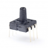 | Via Amazon | |
| Male-to-Male Jumper Wires | 10 | 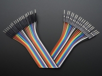 | Via Adafruit |
Materials:Electronics (Soldered)
| Name | Quantity | Picture | Link | Notes |
| Arduino Micro | 1 | 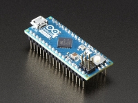 | Via Adafruit | |
| Half-sized Perma-Proto Board | 1 |  | Via Adafruit | |
| 10KΩ Resistor | 3 | | Via Adafruit | |
| 2.7KΩ Resistor | 2 | | Via Amazon | |
| 1KΩ Resistor | 1 | | Via Amazon | |
| 0.1uF Capacitor | 2 | | Via Amazon | |
| 10uF 50v Electrolytic Capacitor | 2 | | Via Amazon | |
| LM358 Dual Op-Amp | 1 | | Via SparkFun | Any of the LM358-series chips will work |
| MPS20N0040D-D Pressure Sensor | 1 | | Via Amazon | |
| 22AWG Solid-Core Wire | at least 10" | 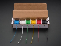 | Via Adafruit | |
| DIP-8 IC Socket | 1 | 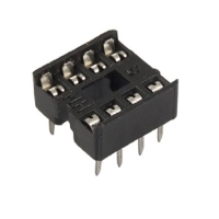 | Via Amazon | |
| Female Headers | 1 |  | Via Adafruit | |
| Solder | 1 |  | Via Adafruit |
Tools:
| Name | Notes |
| Flush Snips | |
| Wire Strippers | |
| Soldering Iron | |
| PCB Vice | Optional, but will come in handy when soldering |
Design 1 Fabrication
This page will go over the steps to create Design 1 of the PDS.
Step 1:
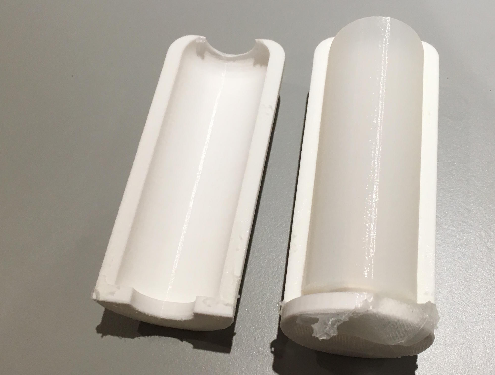
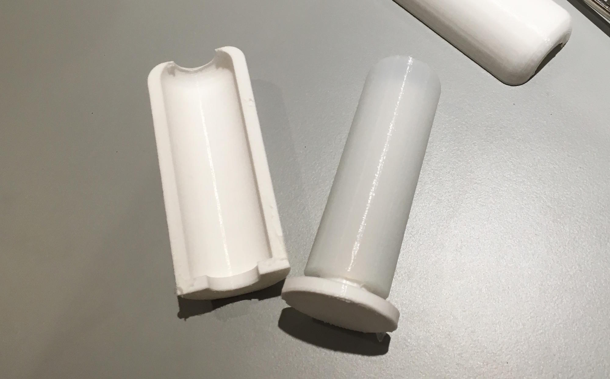
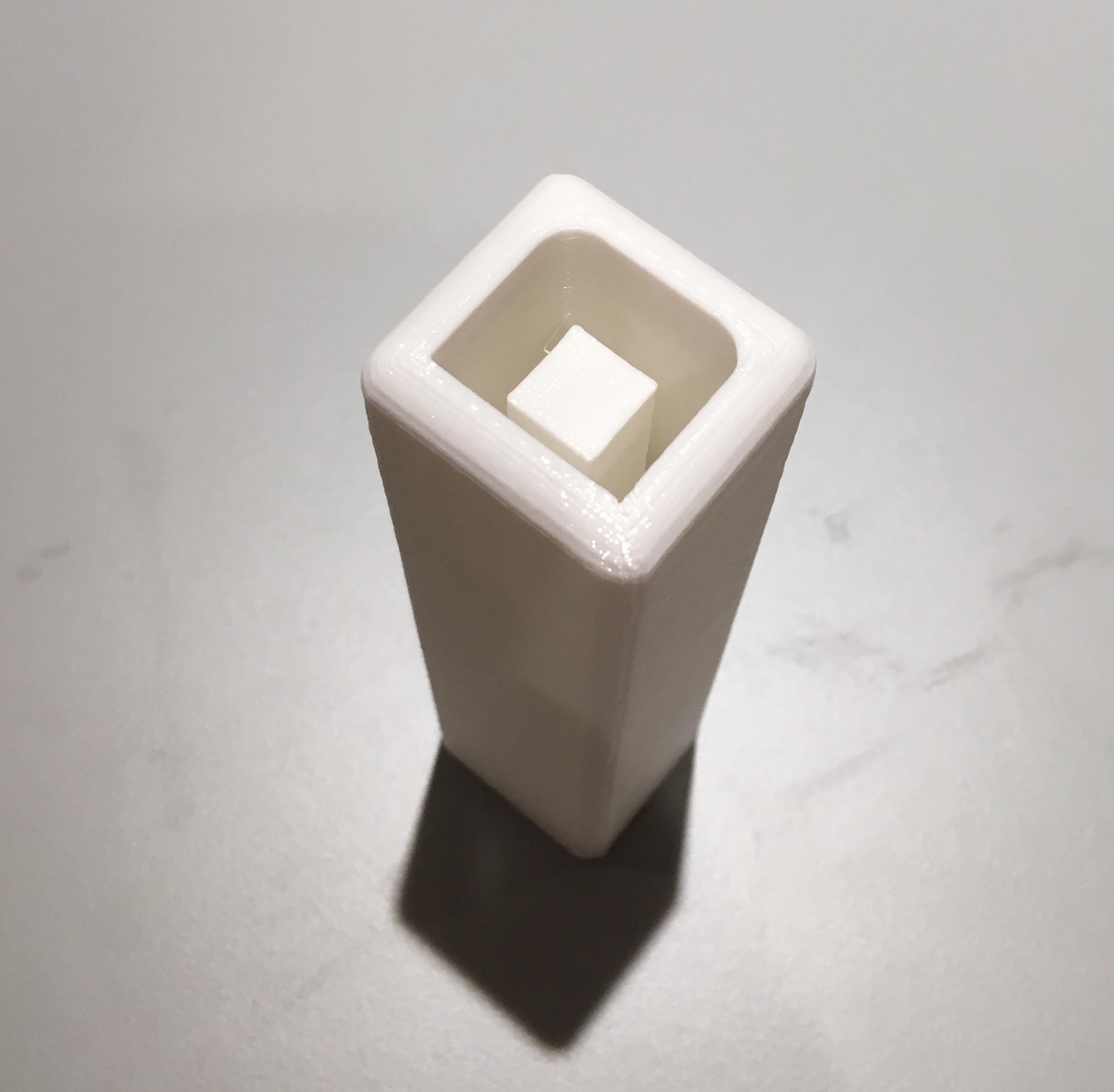
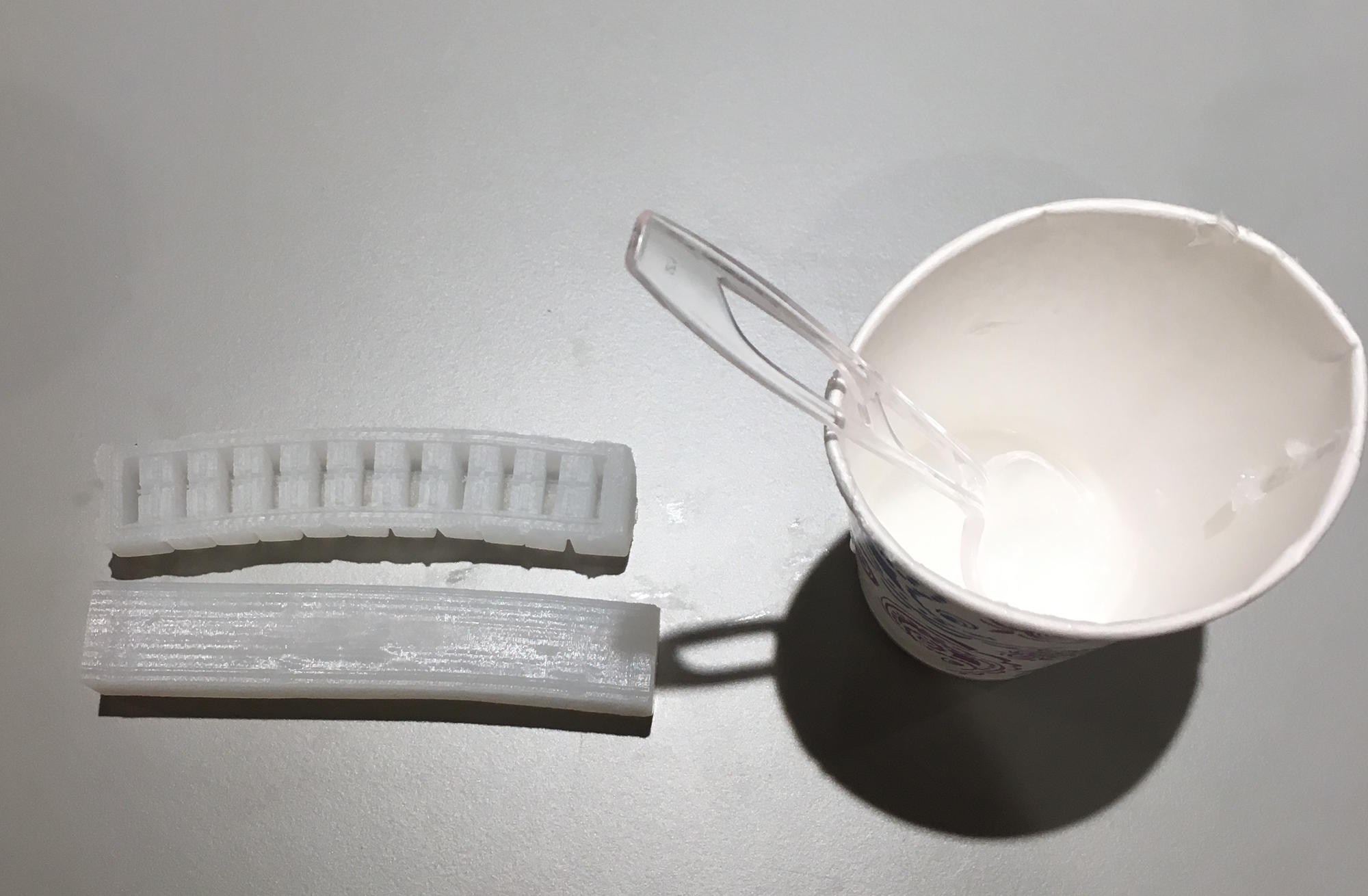
Begin by printing the .STLs for three-part mold that are found on the Downloads page. Print 1x design1_core.STL and 2x design1_outer.STL. Supports are not necessary for printing.
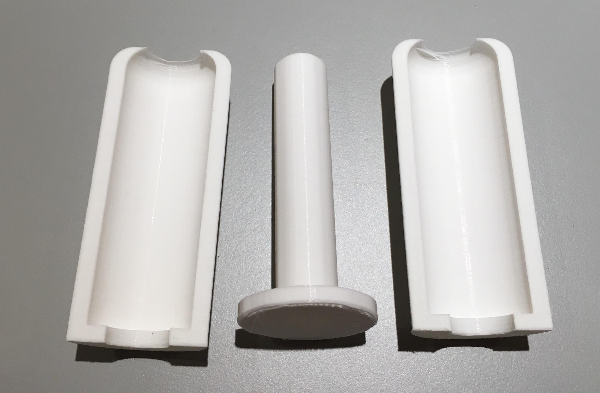
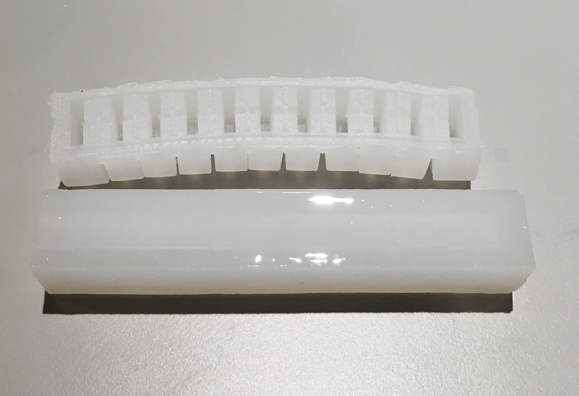
Step 2:
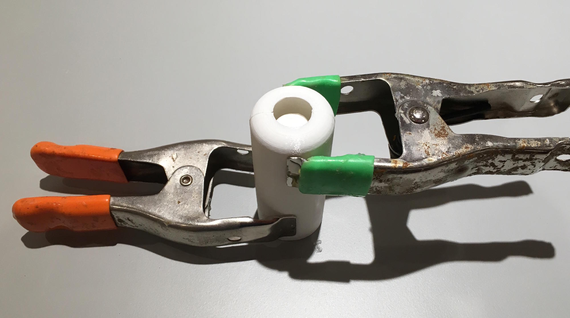
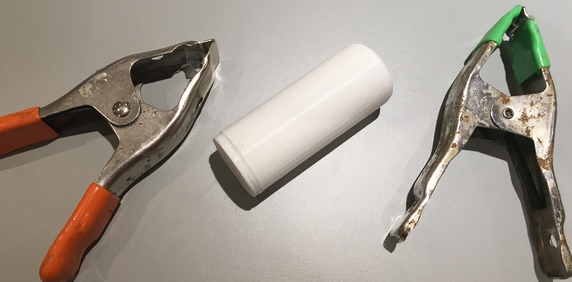
Assemble the mold with the two outer pieces surrounding the inner core. Put the two clamps around the mold.
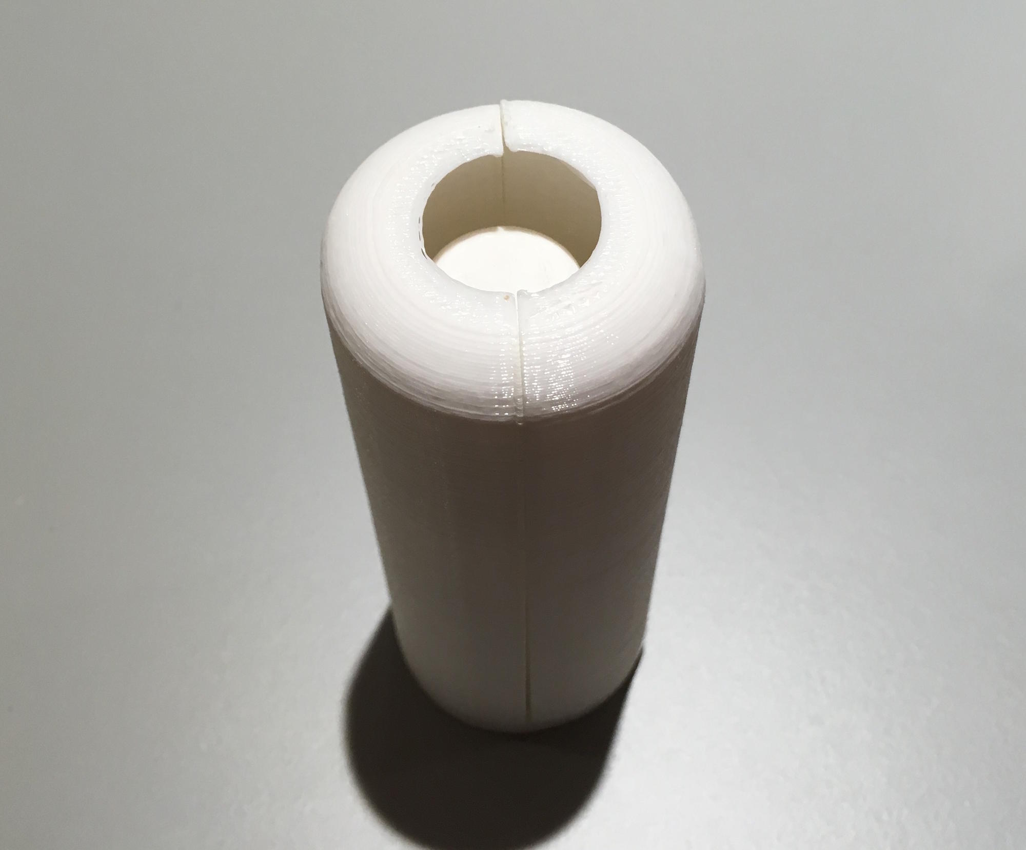
Step 3:
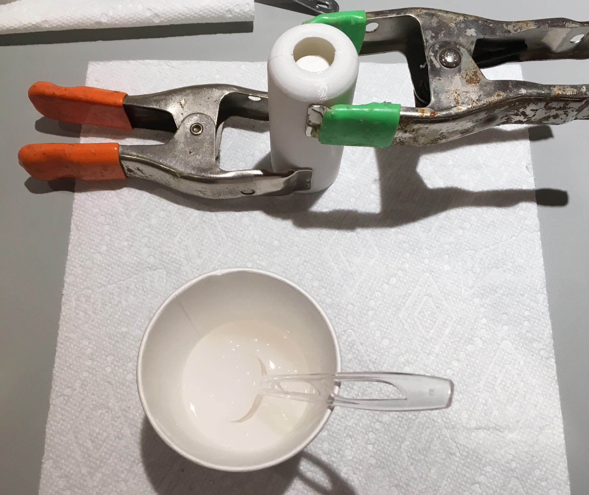
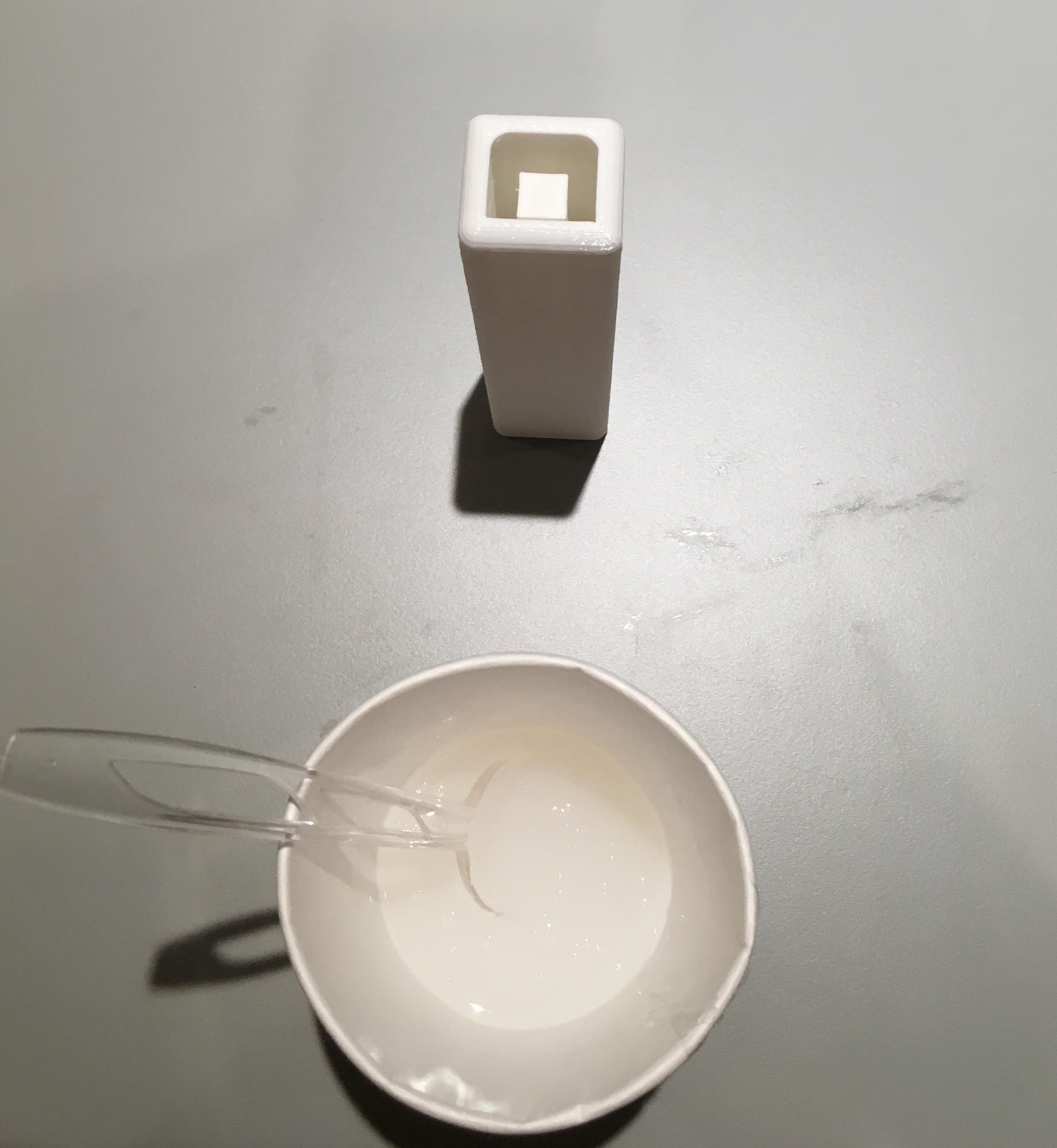
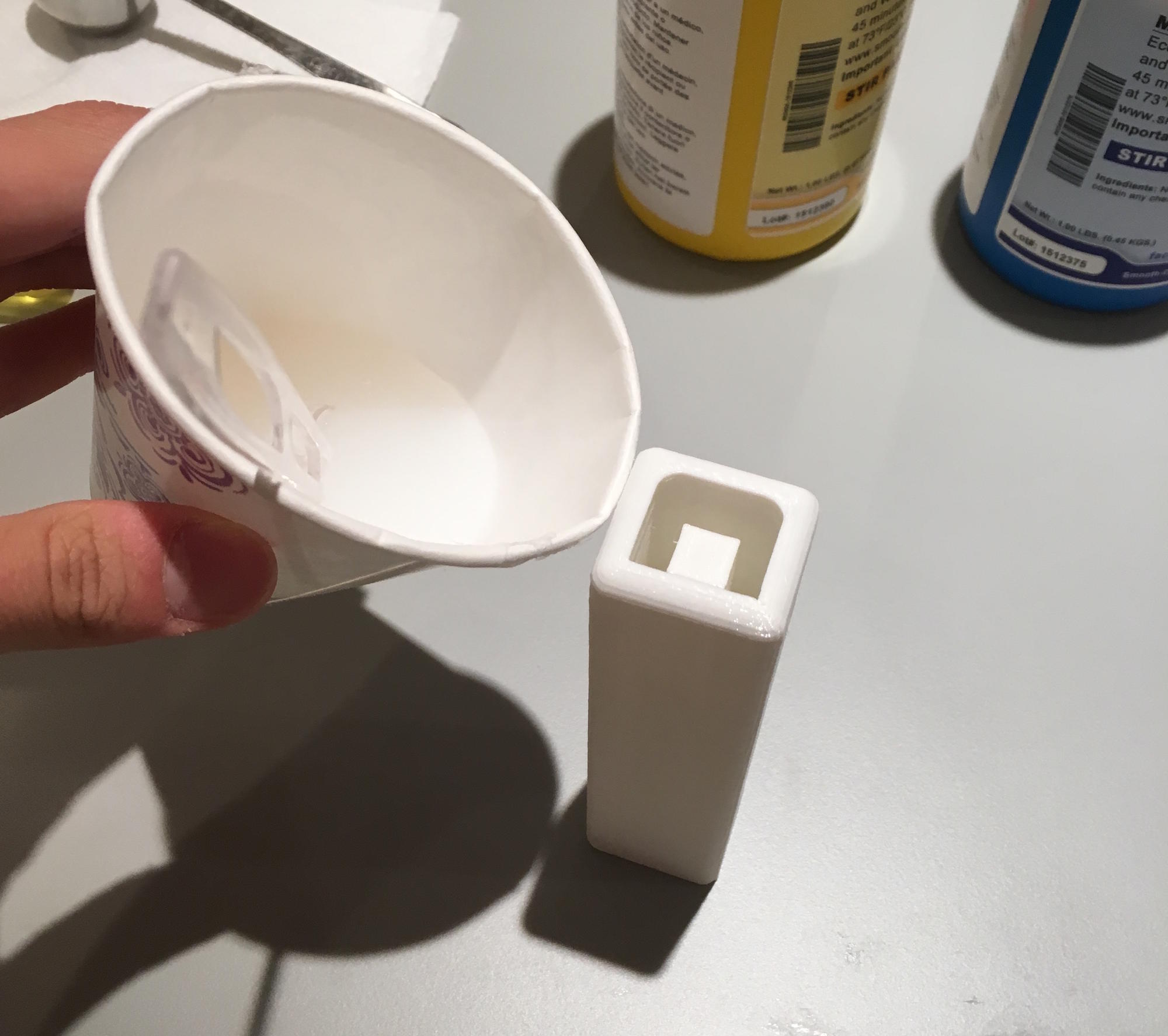
Measure out 25ml of Part A and Part B of the Ecoflex 00-30. Put both parts in a cup and mix together thoroughly with a spoon.
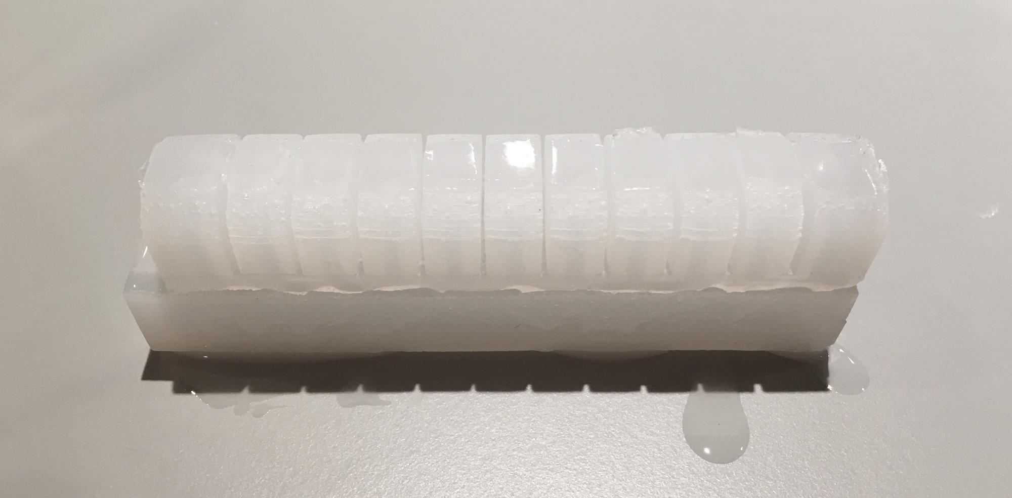
Step 4:
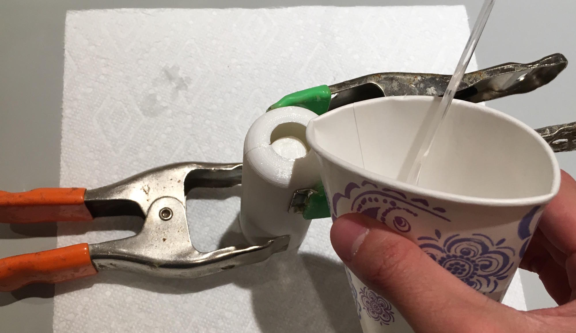
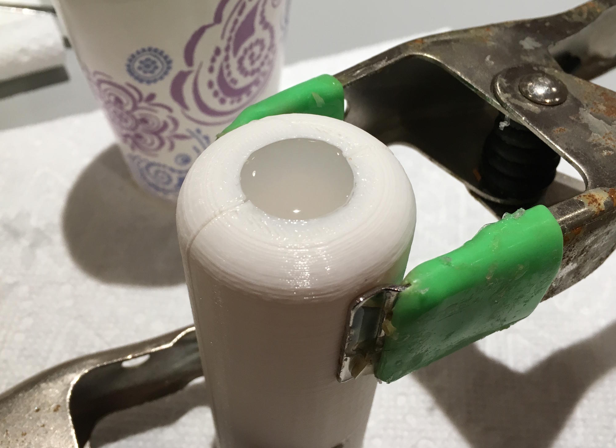
Pour the mixed Ecoflex into the mold slowly and steadily and stop occasionally to let bubbles escape. Fill the mold to the brim. Let the silicone cure for 4 hours.
Step 5:
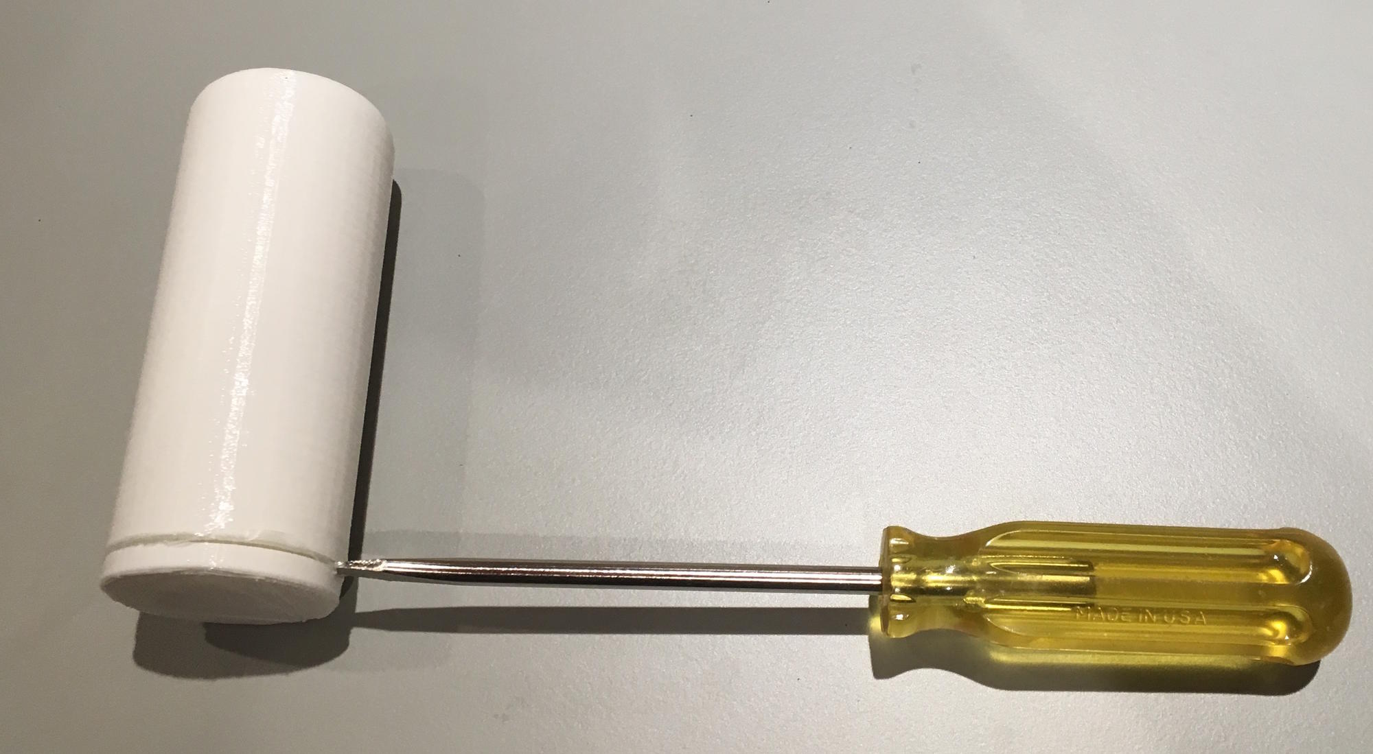
Once the Ecoflex has cured, take the clamps off of the mold and use a screwdriver to pry apart the mold. Pull the cast off of the core.
Step 6:
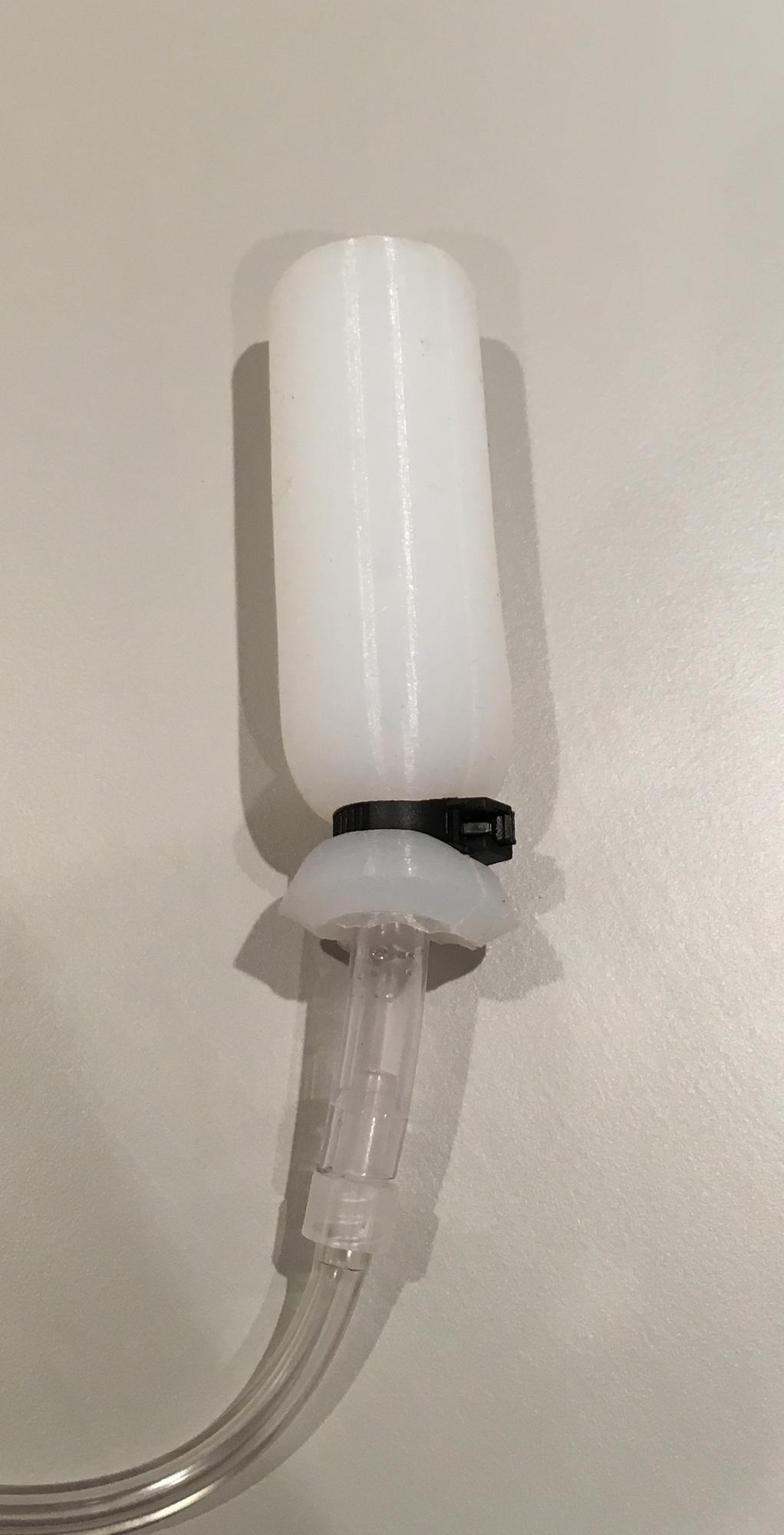
Attach the lengths of 1/4" and 1/8" tubing with the luer fitting.
Step 7:
Insert the 1/4" end of the tube into the open end of the silicone cast. Secure a zip-around around it and tighten it into place, securing the tubing.
Step 8:
Connect the 1/8" end of the tube to the pressure sensor on the electronics.
Instructions on how to operate Design 1 can be found in the Testing section.
Design 2 Fabrication
This page will go over the steps to create Design 2 of the PDS.
Step 1:
Begin by printing the .STL of the mold found on the Downloads page. Supports are not necessary for the print.
Step 2:
Measure out 25ml of Part A and Part B of the Ecoflex 00-30. Put both parts in a cup and mix together thoroughly with a spoon.
Step 3:
Pour the mixed Ecoflex into the mold slowly and steadily and stop occasionally to let bubbles escape. Fill the mold to the brim. Let the silicone cure for 4 hours.
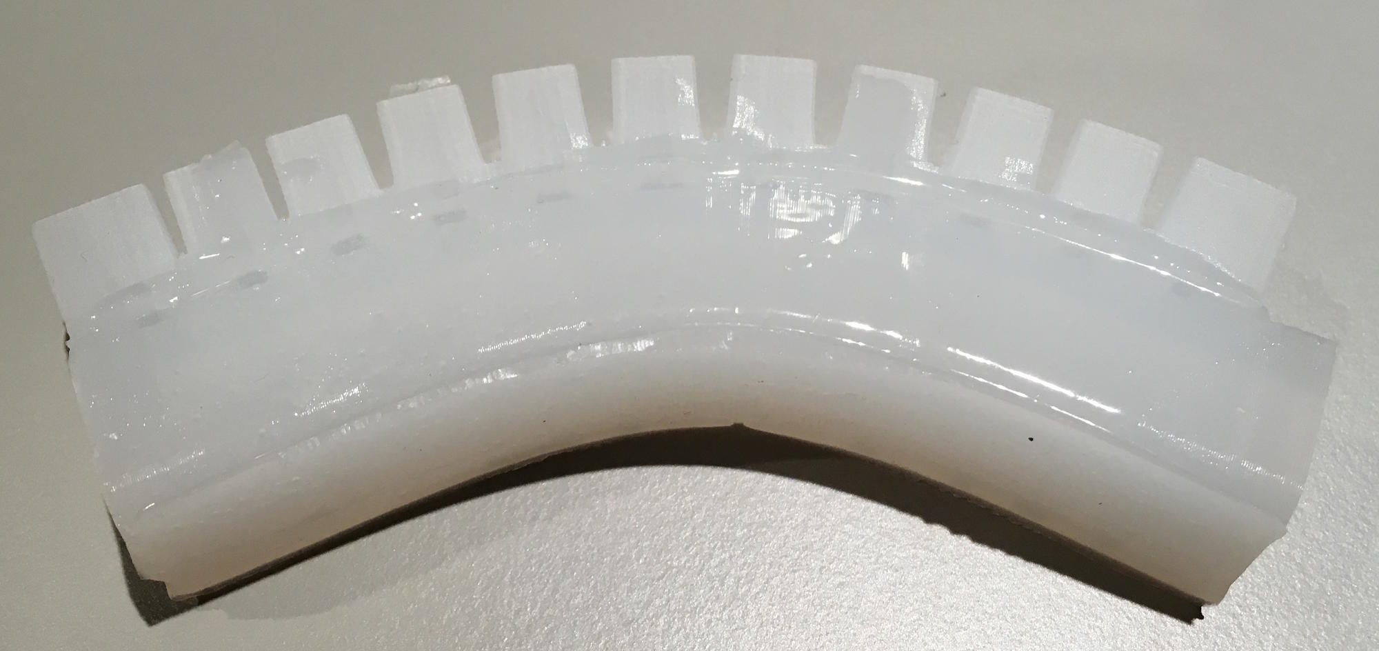
Step 4:
Once the Ecoflex has cured, carefully pull the cast out of the mold. Wiggling the cast back and forth helps to remove it.
Step 5:
Follow the Fabrication guide for the PneuNets Bending Actuator up to "Remove main body from molds" in Step 3.
Step 6:
Mix a very small amount of more Ecoflex. Spread a very thin layer (1mm) of it on the flat side of the PDS. Place the cast of the actuator on top of it carefully. Let the silicone cure for 4 hours.
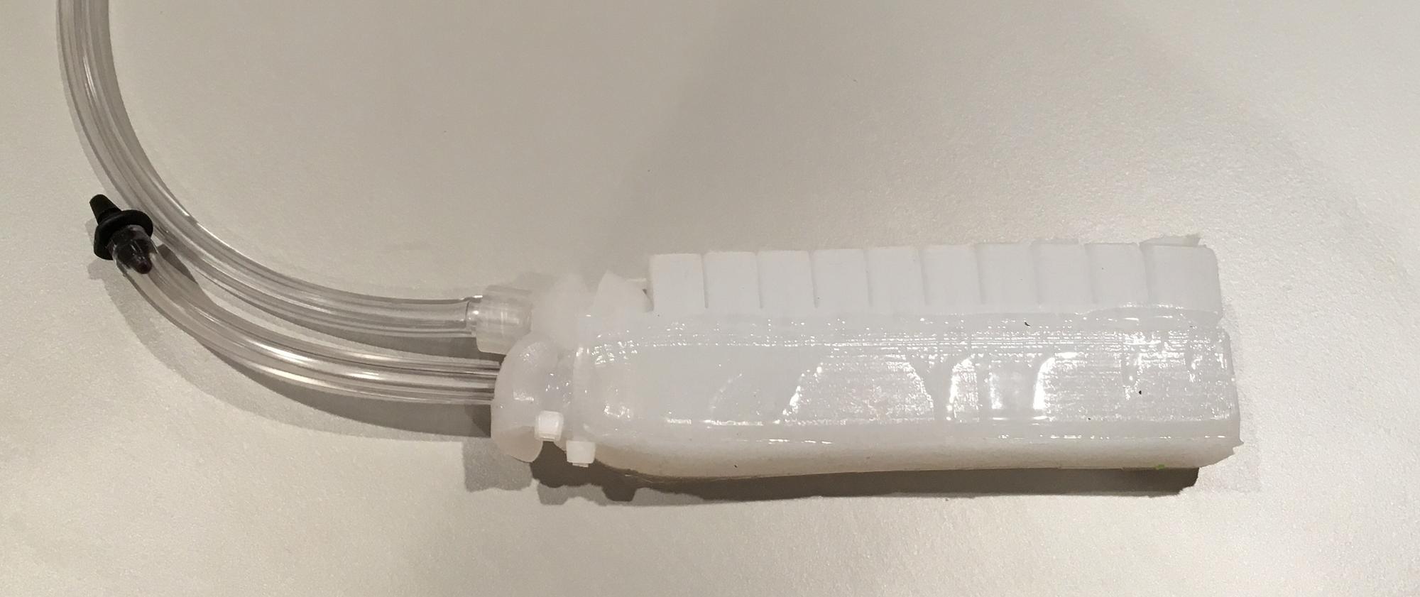
Step 7:
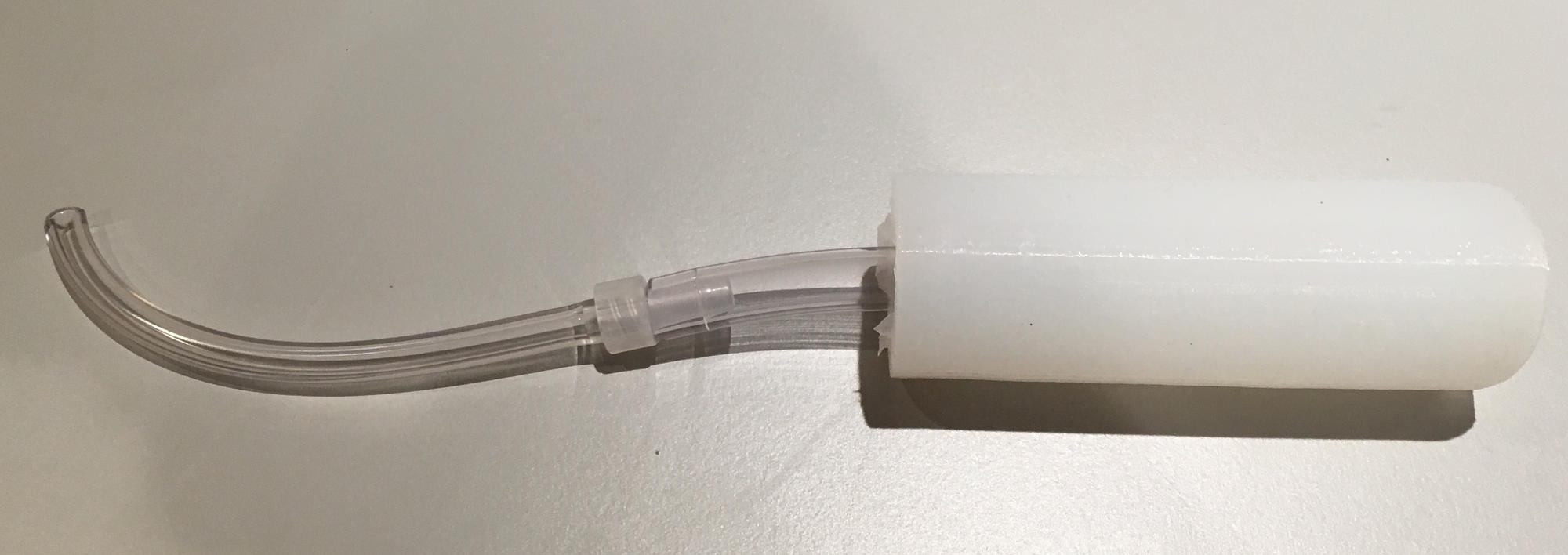
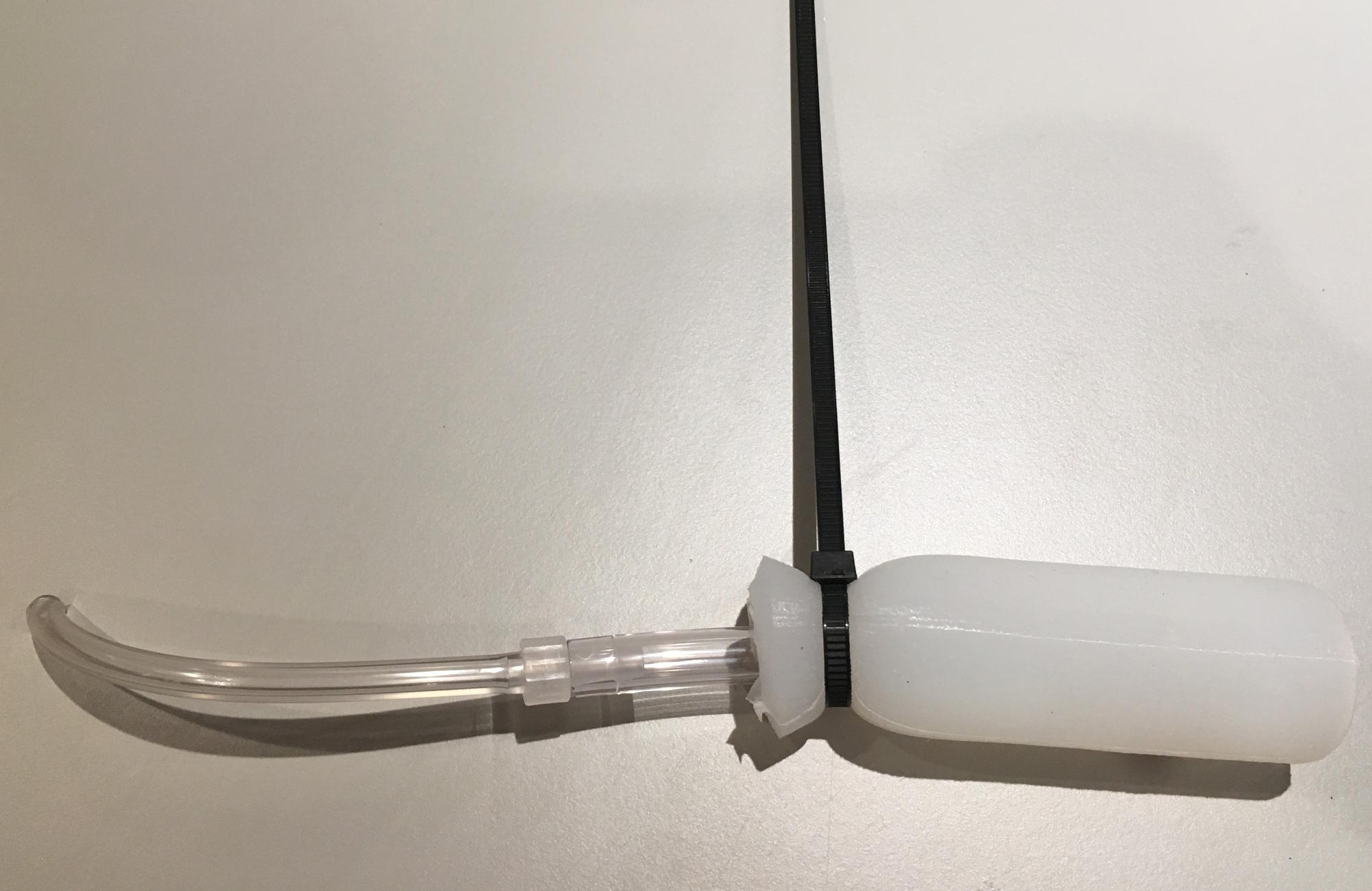
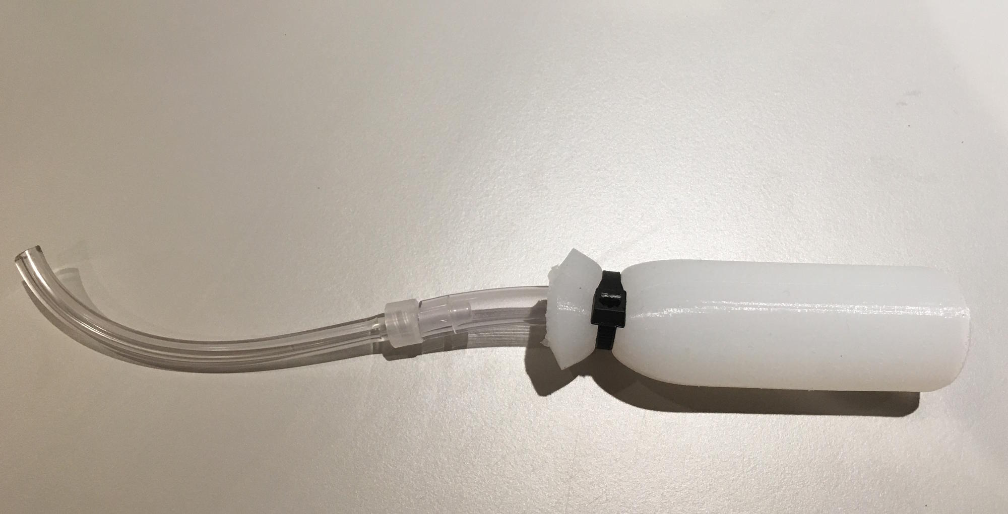
Connect one length of the 1/8" tubing to the Luer fitting. Puncture the end of actuator that is at the same end as the opening of the sensor with a screwdriver. Insert the end of the Luer fitting into the hole. Put one zip-tie around this part of the actuator and the sensor and tighten it only slightly, so that it is held in place. Insert the other length of tubing into the opening of the sensor. Put a zip-tie around this part and tighten.
Step 8:
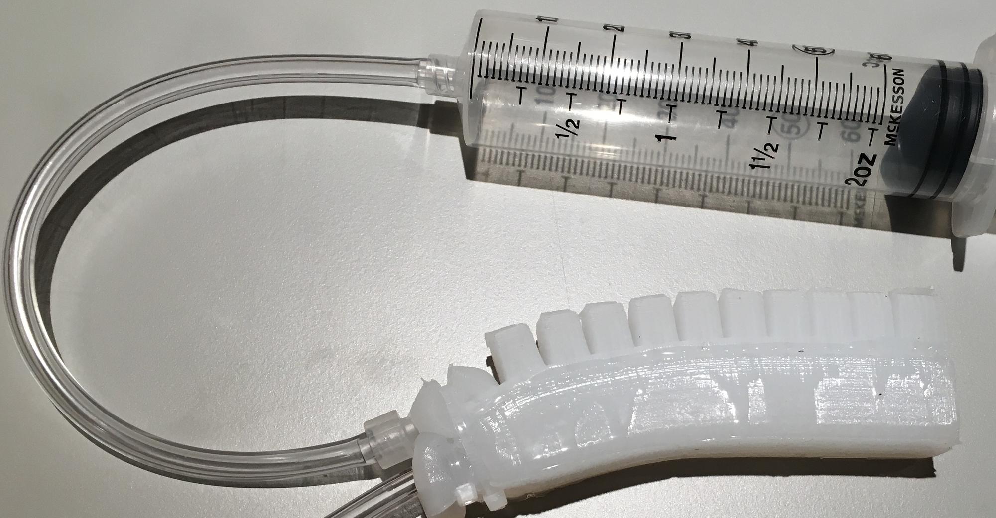
Connect the tubing from the actuator to the air source (syringe, air compressor, squeeze bulb) and connect the tubing from the sensor to the electronics.
Instructions on how to operate Design 2 can be found in the Testing section.
Electronics Fabrication
This page will go over the steps to create the breadboard and the soldered versions of the electronics.
Breadboard
To build the electronics on a breadboard, follow the breadboard diagram and circuit schematic below.
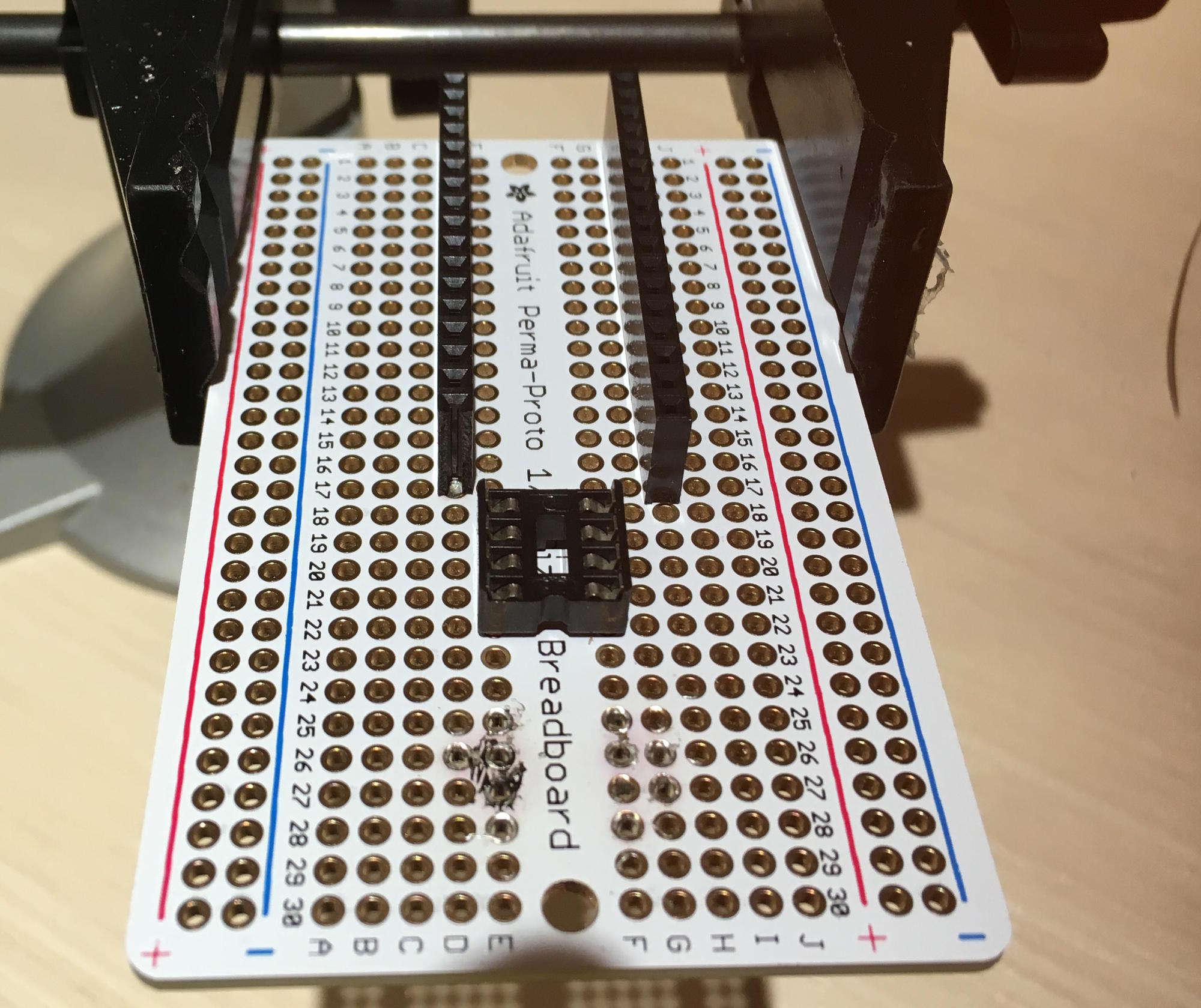
Soldered
To build the electronics on a soldered Perma-Proto board, follow the breadboard diagram (Perma-Proto boards and breadboards have the same layout) and the circuit schematic.
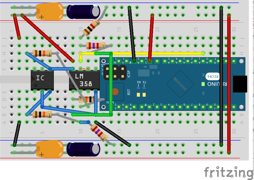
Remember that the Arduino and the LM358 IC are not soldered directly in. Female headers and DIP sockets are soldered in instead.

Testing
Design 1 Operation and Testing
To operate Design 1, start by connecting the electronics to the a computer with the Arduino IDE installed via a USB cable. Upload the code found on the Downloads page to the Arduino board. Open up the serial monitor in the IDE and the pressure readings should start coming through. Compressing and squeezing the sensor will cause the pressure readings to increase up to a maximum of 10 PSI.
Design 2 Operation and Testing
To operate Design 1, start by connecting the electronics to the a computer with the Arduino IDE installed via a USB cable. Upload the code found on the Downloads page to the Arduino board. Open up the serial monitor in the IDE and the pressure readings should start coming through. Inflating and actuating the PneuNets Bending Actuator will cause the Pneumatic Deformation Sensor to provide 1 PSI of feedback.
Weight-Pressure Relationship of Design 1
Increasing weight was put on the Design 1 sensor starting from 15lbs in order to test how weight on the sensor affected the pressure read by the sensor.

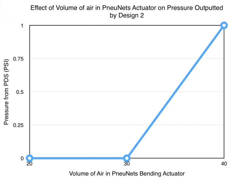
Actuator Volume-Pressure Relationship of Design 2
Increasing volume of air was pumped into the PneuNets Bending Actuator of Design 2 in order to test how the actuators inflation affected the pressure read by the sensor.
Use of PDS with an Automated Control System
One of the purposes for creating Pneumatic Deformation Sensors was to develop an easy method for feedback from soft actuators. This feedback could be used in conjunction with a pneumatic control system to allow the actuators to be smart and more precise. This is shown in the following video, in which the PDS electronics communicates with a pneumatic control system to consistently inflate the actuator. When the sensor detects a pressure higher than 1 PSI, it tells the control system to stop inflating and drain the actuator of air. This results in a very uniform actuation that proves that PDS's can be used as an effective means for feedback in soft robots.
Downloads


| mps20n0040d-s_datasheet.pdf | 276 KB | |
| pds_code.zip | 755 bytes | |
| lm358_datasheet.pdf | 1009 KB | |
| design_1_.stls_.zip | 484 KB | |
| design_2_stl.zip | 160 KB |