Design Overview/Requirements
The concept behind the designs are to emulate the natural eyeblink to maximal degree possible. Specific designs are discussed in their subpages, overall requirements and a description of anatomy is provided here.
Natural Eyeblink
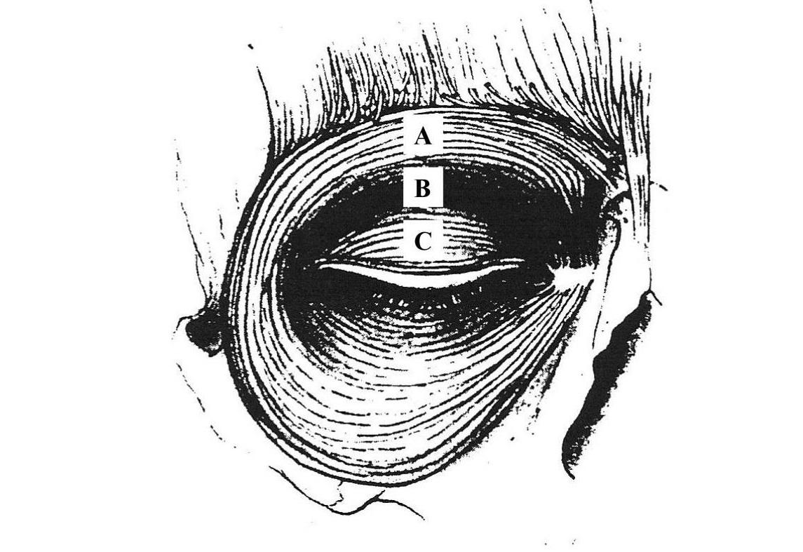
Eyelid closure occurs naturally via the activation of the sphincter like orbicularis oculi (OOc) muscle (pictured above, image from Grey's Anatomy). The eyelid is kept tonically open via the levator palpebrae superioris muscle (LPS) which becomes inactive during the blink impulse. The eyelid is brought downwards slightly due to passive muscle tension prior to activation of the OOc. The contraction of the sphincter like OOc muscle around the eyelid pushes folds of skin in the eyelid downwards and closed in a complex motion.
It should be clarified - the design is not required to account for eyelid opening. The LPS is generally unaffected and can open the eyelid open, only closure needs to be addressed.
Other key requirements are outlined.
Effectiveness of Closure
The device should achieve full closure. The force and displacement requirements are difficult to estimate as the vary for different closure mechanisms. However, for the linear sling design used by Tollefson and Senders to create an implantable closure device (effective on cadavers), force requirements were 654mN and 8mm closure (see reference [2] in Background). The actuator should ideally (although not necessarily) exceed these minimum requirements.
Closure should ideally occur within 80-100ms (natural closure times), however slower times are acceptable.
Ease of Use & Comfort
The device should be easy to apply and remove.
Closure should not be uncomfortable.
Safety
The device should not apply excessive force or displacement such that tissue is injured. It shouldn't cause irritation over long term usage (although this is hard to measure in this study.
1. Force transfer by constrained string - (Main Design)
Overall Design Summary:
A string based design which creates a sphincter like closure motion is described in the below Figure. A patch with holes, or struts for connector string to pass through is attached to the rim of the eyelid. On either side of the eyelid, the string is constrained. When the string is pulled from its lateral attachment and forced to tighten the eyelid is also forced downwards, as the tightening creates a downwards motion on the struts and hence the eyelid. This method could be extended to the lower eyelid to create a full sphincter like motion.
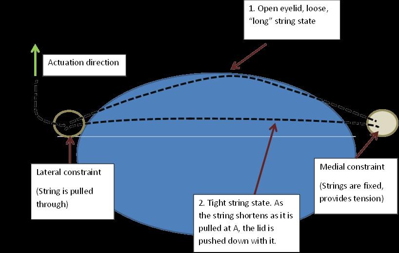
To skip a few steps, how it looks in the end (without the actuator) is shown in the figure, below. 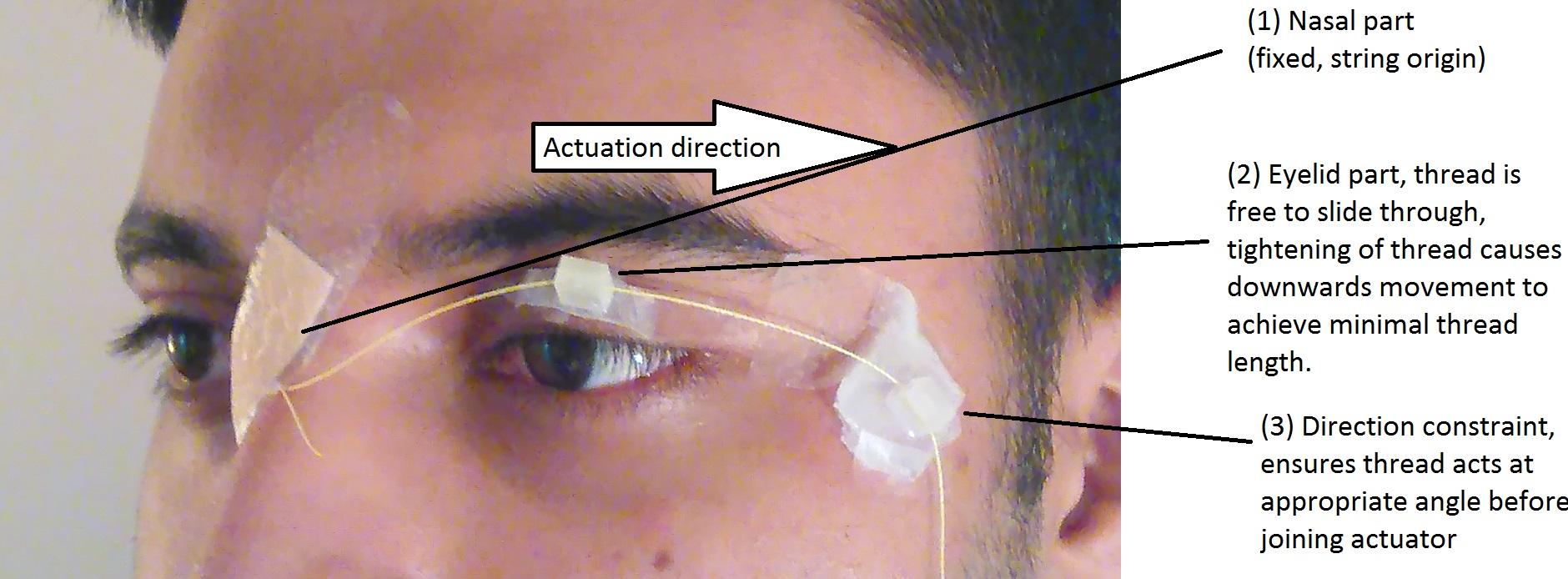
It is important to note - here the string being pulled sideways creates a downwards force on the struts and hence the lid (as opposed to a side/lateral force). The string is fixed at the nasal point in a ball of epoxy and is allowed to slide through the attachment on the lateral side of the eye (such that it is constrained to pass through a comfortable direction before reaching the actuator situated on glasses.)
Disadvantages of and Modifications to Design
Key modifications and areas for future work are described in the "Testing" section outlining results and whether the device meet spec.
Some possible modifications, alternate designs, or work leading to this design are discussed in the alternate design subsections.
However, it is immediately apparent that alterations to geometry (e.g. thicknesses of moulds and size of struts, or positioning of elements on the face) could be optimised to a greater degree than they have been here.
Materials
Patch Related Materials
Ecoflex Silicone elastomer was used to fabricate the patches. This was due to the material being FDA approved for skin contact, while being (sufficiently) strong while still highly compliant. The patches are required to be highly flexible to conform to skin surfaces while bearing some load. 00 and 05 grade silicones were tested - 05 was used as 00 tore a few times during the fabrication process, as the parts were very thin to maximise comfort. The greater the mass/volume on the lid, the greater the noticeability of the device.
During manufacture, 3D printed (some with resin, some using ABS) struts with holes/channels inside were embedded into the structure during curing. This was to provide a smooth, strong and low friction surface (in contrast with silicone) through which the fibre could pass through. Low friction is important - having a sticky surface would mean some of the lateral movement of the fibre would be transferred to the patch. Using normal pneumatic tubing was considered, but there was a tendency for it to stick to fibre and not slide through smoothly.
Kevlar thread was used as the "string" to transfer force. This was mostly due to it being smooth and not liable to fraying, making it easy to thread into tubing and struts. Household string could have been used instead.
Clear Band-Aid was used to attach components to skin due to its biocompatibility and easy of use. Other medical grade adhesives were considered, but were more difficult to work with in the fabrication process.
Glasses/Actuation Materials
A standard pair of laboratory safety glasses were used as the testing glasses to which the actuator was attached.
A linear actuator capable of 20mm of actuation (in 800ms) from Firgelli Motors (PQ-12) was used as the actuator. While this is slower than that the closure time of the eyelid (80ms), this is sufficient for proof of concept testing. A commercial control board supplied was Firgelli was used for control.
Connector materials
To wear the device, first the patch/es are applied, then the actuating glasses are worn and the two are connected. Both are separate. To facilitate their connection, pneumatic tubing (connected to the patch end of the fibre) and a luer lock (connected to the actuator fibre) were used as connections. When both components are ready, the luer lock and the tubing are connected, interfacing the two components and allowing for force and displacement transfer.
Geometry
Relevant Component Geometry
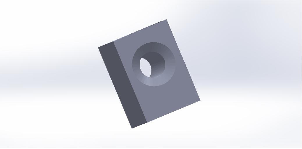
STL files for the patch moulds (for fabrication with silicone elastomer) and the 3D printed struts are provided here (as this wiki does not support the upload of STL files) :
https://drive.google.com/open?id=0B3gYzJ0u42Q4TjNMWlJ0Q3NOczA
The ideal patch dimensions for the current user (the author) wasn't known. Some guesses were made using anthropometry to construct a number of patch moulds with various widths and heights and the most comfortable/ergonomic patch for the author was chosen. The key factors were that it should be smaller than the lower fold of the upper eyelid - if it covered the entire lid the eyelid wouldn't be able to "fold out" to close. A patch with a height of 12mm and width 24mm was chosen. The depth was assessed by fabricating a number of patches and determining what was the minimum depth at which struts could easily be incorporated during moulding.
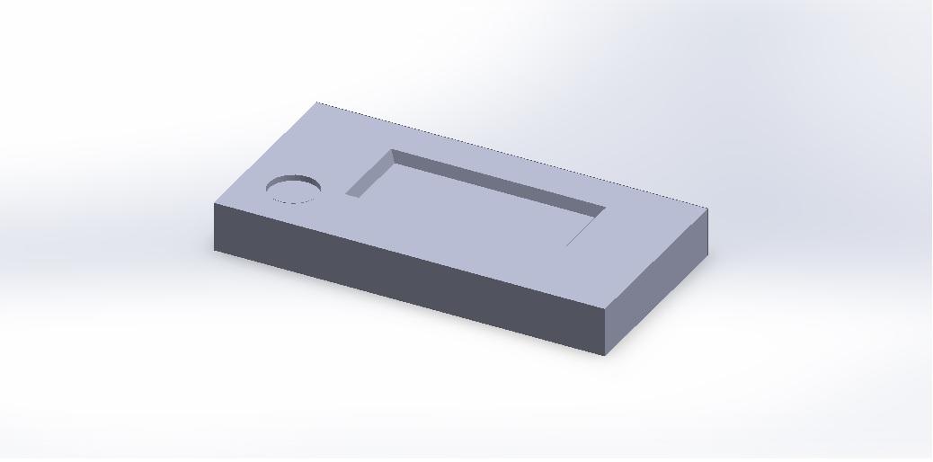
A mould image and "strut" image are provided below:
Overall Positioning of Patch on Lid
Nasal Patch: This consists of a patch of silicone, connected to the skin by bandaids with an epoxy patch from which the kevlar fibres emanate. It is positioned on the rigid contralateral side of the nose. This a fixed end point for the fibre which provides the reaction force and hence tension that creates a downwards force upon the struts during lateral pulling of the string.
On eye patch: This is positioned on the lower half of the upper eyelid, which folds down upon closure of the lid. As stated, downwards movement of the strut will push closed the lid.
Lateral constraint: From preliminary designs assessed in "Side Project - Lateral Pulling", it was determined that a 45 degree angle of depression from the mid line of the eye (directed slightly posteriorly) provided the most "comfortable" closure for the author. As such, there is a patch with an embedded strut positioned on the side of the eye. The fibre passes through this, constraining the direction of fibre pulling relative to the lid, prior to passing to the actuator.
Manufacturing
Molds were designed in Solidworks and 3D printed. Silicone elastomer was cast in these molds and cured in an oven at 60 degrees for 15 minutes. Prior to curing, struts were pushed into the silicone such that they were embedded into the final cured structure.
The manufacturing process used shall be described in greater detail in the fabrication section.
2. Lateral Pulling (Preliminary Design)
Background and Overview:
Prior to attempting the main soft exopatch device, the concept of external eyelid closure was explored by considering the possibility of achieving closure by attaching a connector to the lid (e.g. a Band-Aid with string) and pulling laterally using an actuator.
The linear sling method, using a sling harvested from temporalis muscle fascia, has been used to create a working prototype of implantable active closure devices using electroactive polymers [2].
It involves harvesting patients muscle fascia, inserting it into the eyelid and pulling it laterally to drag the eyelid closed. A schematic (taken from Tollefson and Senders, 2007) outlining the concept is shown below.
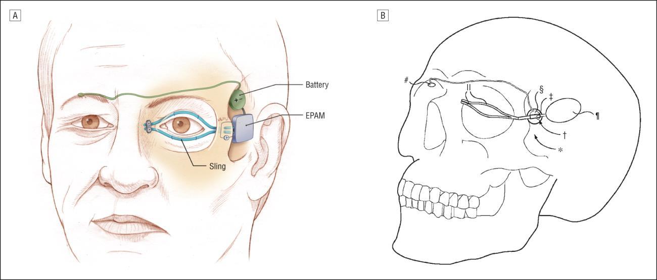
It may be possible to use the same method to provide closure externally, by attaching a lateral pulling actuator to the external surface of the upper eyelid, possibly using string and Band-Aid for purposes of prototyping.
To achieve closure using an implant device, a linear actuator, must provide 6mm of unidirectional displacement and 654mN of force to a sling inserted into the upper eyelid [2].
The proposed method could involve the following key materials and geometry:
- Actuator: A linear actuator situated laterally to the lateral canthus of the eye, (able to achieve 6mm of displacement)
- Method of Attachment: String, attached to the inferior palpebral portion of the upper eyelid
- Closure Motion: Transfer of force and displacement from the linear actuator to the upper eyelid via the string.
The key requirements, are as follows:
- Actuation Displacement: Either 6mm lateral displacement, or a 6mm vertical displacement component. There is dispute regarding this requirement.
- Force: 20-100gmf force if activated simultaneously with blink, 56-150gmf force if activated while the levator is active
- Actuation Time: Ideally within 80-100ms
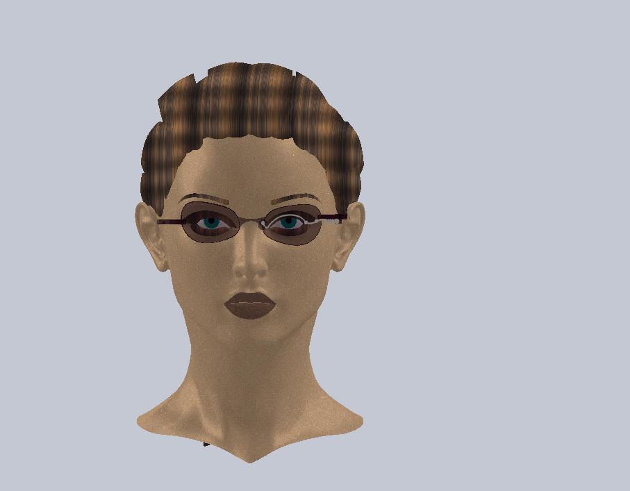
The device is illustrated as per the following general schematic, representing the actuator connected to some element on the lid. The actuator would act in the right hand direction of the image.
3. Pneumatic Exopatch - (Failed Design)
This design consists of thin patches of eye-shaped, high durometer (very soft) silicone (<1mm thickness) with an air chamber inside. The Figure below explains its concept of operation.
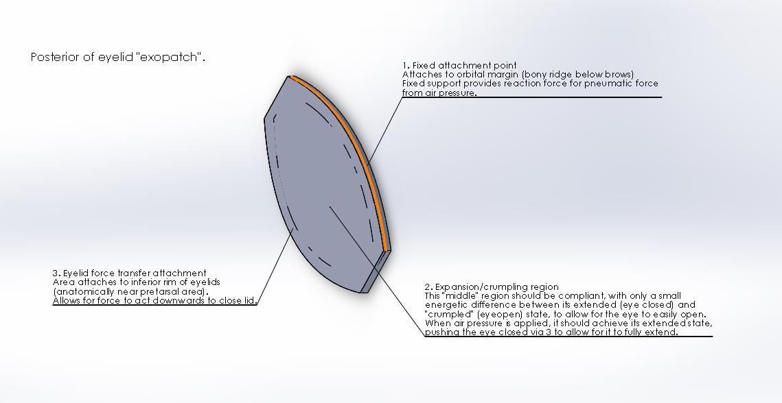
Figure : Design description of pneumatic exopatch
A cut-out section of the unassembled patch in illustrates the top and bottom layers and the air pocket in between.
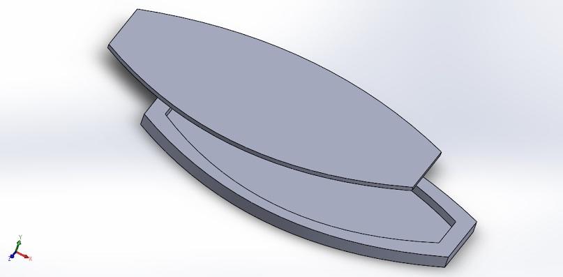
Figure: Cut-out of unassembled patch.
Improvements may be made by introducing channels in the design with strain limiting sections (e.g. with embedded stiff fibres) in between which can limit the expansion to occurring purely axially. A key challenge will be designing patches which can expand enough to provide closure while also being "strain free", or comfortable, while the eye is open.