Testing
The validity of the final concept involved testing the effectiveness of closure as well as human-subject testing for comfort and usability. The results of this data are listed in the subsequent pages.
1. Force transfer by constrained string (main design) - Results and Testing
The ideal method of testing the device would be to trial the device on patients with impaired blinks. However, due to the lengthy ethics approval processes required, patient testing of the device is not considered in the scope of this study.
Preliminary testing, to assess the relative effectiveness of closure methods to advise future study, was conducted by trialling the device on the author. The degree of closure and measures such as “comfort” and "ease of use" were considered.
Testing without actuator
Prior to attaching the actuator, the mechanism of closure was tested. Specifically, the following question was addressed:
Can a thread pulled through a system of patches with:
- patch (1) fixing the thread origin on the nasal side;
- patch (2) transferring downwards force to the eyelid; and
- patch (3) ensuring the direction the thread was pulled was constrained
achieve eyelid closure?
This was tested by applying the patches in the described configuration and pulling the thread. The following video demonstrates the results.
This demonstrates that actuating the thread connected to the patch configuration is able to generate closure.
It was noted here that the patch on the eyelid was being slightly disconnected, this was corrected by applying more band-aid adhesive. It could be beneficial to have adhesive running across the entirety of the underside of the patch for more even attachment. It would be desirable in future to test the effect of various constraint positions on the closure.
Whether a system of patches actuated by a linear actuator is capable of achieving closure:
The actuator/glasses device outlined in the fabrication section was worn and connected to the patch thread via luer lock/tube attachment. During testing the thread was disconnected from the luer lock - the thread was reconnected directly to the actuator (as observed in the results videos). The thread was in a resting state such that applying a small amount of displacement to it would result in creating some tension on the eyelid.
The actuator was activated to provide a posterior stroke, increasing from 6mm - 16mm. Partial eyelid closure began to be observed from ~8mm stroke.
Full closure was observed from 14-16mm stroke.
Discussion
Effectiveness of Closure:
Full closure was achieved using 16mm of closure.
Lower levels of displacement were not sufficient to achieve closure. This is double the Tollefson and Senders value of 8mm for linear sling based closure. It is expected that this is due to the displacement required to take up passive eyelid tension. Some displacement needs to be applied to the eyelid to take it from a "comfortable" stress-free state to a taut state prior to movement causing eyelid closure. This should be considered in device design. It is expected that the displacement requirements will vary from person to person, and also between applications of the device (e.g. through altered constraint positions). It would be of benefit to assess these variables through a study on multiple real people, where constraint positions are systematically varied and required displacement is observed.
The closure did not meet the 80-100ms goal to replicate natural eyelid closure (it is expected approximately 600ms was the time).
Comfort & Ease of Use:
While the device was noticeable, the closure motion did not elicit discomfort.
However, the ease of use was very low. It was challenging attaching the patches in the right configuration, with adequate adhesion, and then connecting the actuator system. It took over 5 minutes to apply the device and occasionally de-adhesion would occur.
Two key areas require work:
1) An easy "on-off" interface system to allow application of the device
2) More effective materials selection and fabrication processes to allow for more reliable and easy to apply adhesion.
Validity of Self Testing:
The prototype devices were self-tested on a team member. It is possible that confirmation bias exists in reporting subjective values such as “comfort” and “noticeability” due to the involvement of the test subject (the author) with the project.
It was noticed that the right (unactuated) eyelid drooped slightly in time with the actuated eye on closure, this is likely due to the eyelids LPS muscle relaxing. This is similar to how the eyelid of an impaired patient would behave (where the LPS will relax but the eye will not close fully).
It is also likely that reporting on subjective parameters such as comfort may differ across subjects. Given the sample size of 1, it is not possible to determine whether reports on the “comfort” of specific design aspects are transferable to the wider population. For example, some people may feel more or less irritated by the presence of a Band-Aid on the lid.
However, it is believed that the results are still valid and useful for early stage design decisions and demonstration of proof of concept. Details, such as the amount of displacement required and optimal location of attachment, are likely to vary and need to be assessed using other subjects drawn from the wider population.
2. Lateral Pulling Results and Test Methods (Preliminary Design)
The ideal method of testing the device would be to trial the device on patients with impaired blinks. However, due to the lengthy ethics approval processes required, patient testing of the device is not considered in the scope of this study.
Preliminary testing, to assess the relative effectiveness of closure methods to advise future study, was conducted by trialling the device on the author. The degree of closure and measures such as “comfort” were considered.
Results and Discussion
8mm Unidirectional
The closure achieved using a test device fabricated with a button activated 8mm displacement actuator is shown in Figure 4.

A video of the button activated closure is shown:
The lid appears to be fully closed. The test subject reported the following:
Parameter | Recording |
Closure (without pre-displacement) | Complete |
Visual Noticeability | Difficult to notice in normal daylight, especially from a distance past 3 metres. |
Pre-stress Required | Yes |
Pre-displacement Required | No |
Noticeability (Comfort of Active Closure) | Closure from specifically positioned actuators felt natural |
Noticeability (Passive Resting Comfort) | Slightly uncomfortable on pre-stress. |
Dependence of closure on positioning | Dependent on positioning, slight maladjustment results in incomplete closure |
Comfort along various directions
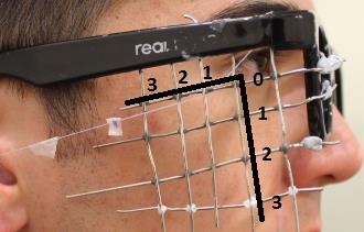
It was expected that various closure directions would provide varying degrees of comfort. To test this, the string was passed through a grid prior to attachment to the actuator to constrain different directions.
The author graded the locations as most ideal, acceptable or uncomfortable. Ideal was defined as not noticeable, acceptable was defined as noticeable but not uncomfortable and unacceptable was defined as uncomfortable.
| 3 | 2 | 1 | 0 |
0 | unacceptable | unacceptable | unacceptable | acceptable |
1 | acceptable | ideal | ideal | acceptable |
2 | acceptable | ideal | acceptable | acceptable |
3 | Untested | Untested | acceptable | unacceptable |
The table coordinates correspond to the grid positions represented in the below Figure.
6mm displacement closure
Full closure could not be achieved without an uncomfortable level of pre-stress being applied to stretch the eyelid prior to actuator activation.
Test Method
1) Prepare electrical components
- The benchtop power supply should be tested with a potentiometer to ensure it is set at 10V.

Figure 3‑3: Benchtop power supply with push-button MAD controller attached.
- The power supply should be connected to the MAD controller through a good electrical connection
- The MAD controller should be connected to the actuator through a good electrical connection which is isolated and unable to contact human tissue.
2) Connect a string to the moving portion of the actuator.
- Tie a knot with the attachment string onto a cavity present on the metal surface of the moving component.
- Fix with the band-aid
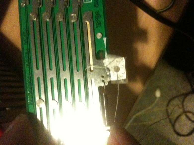
Figure 3‑4: Fixation of string to actuator using Band-Aid
3) Attach the string to the upper eyelid
- Wear the test glasses.
- Place a light amount of blu-tack onto the non-SMA containing (back) surface of the actuator.
- Lightly affix the actuator to some position on the glasses using the blu-tack, such that the attachment string on the actuator can easily reach the entirety of the upper eyelid. Take care to avoid excessively compressing the blu-tack, this will make the device more difficult to remove in subsequent steps.
- Prepare a cut, with approximately 2-3mm width and 10-15mm length, of transparent bandaid adhesive.
- Place the attachment string on the upper eyelid and affix it onto the lid using the clear bandaid adhesive. Take care that the “long side” of the bandaid follows the length of the string. Ensure that the string adheres to as much of the upper eyelid as possible.
4) Reposition the actuator so that the string is taut.
- Remove the actuator from the glasses, taking care to ensure that it still remains near the eyelid. Ensure that the blu-tack is still present on the back surface.
- Keep the eyelids fully open.
- While keeping the actuator near the handles of the glasses, increase its distance from the eyelid until the attachment string is taut.
i. Ensure that there is no stress on the eyelid in its fully “open” state.
ii. The line of action of the string to the eyelid should be approximately parallel to the horizontal plane of the body. This can be judged by whether the top of the actuator is approximately parallel to the handles of the glasses.
- Firmly affix the actuator to the glasses using blu-tack by compressing the blu-tack between the actuator and the glasses.
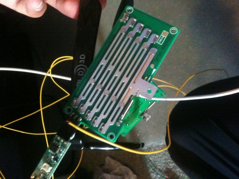
Figure 3‑5: Attachment of actuator to glasses.
5) Apply a voltage to the actuator to generate a closure motion.
- Press the button on the Miga Motors MAD controller to apply 10V from the standard bench top power supply.
6) Take note of effectiveness of closure
- Consider the degree of closure achieved. This can be measured through a visual approximation of the level of scleral exposure (in mm), or the rotation angle required to achieve closure (degrees).
- Consider other subjective factors based such as:
i. Adhesion or de-adhesion of the lid to the globe, based on visual observation or its “feeling”
ii. Any blurring of vision post-blink
iii. Comfort of the device (e.g. feelings of pre-stress) prior to the blink
iv. Overall feeling (comfort, similarity to natural blink) of closure motion
7) Adjust and repeat for different pre-stresses and lines of action
- The test has been carried out with conditions of no pre-stress and a horizontal line of action. The string was attached to the entirety of the eyelid. Repeat with
i. Increasing levels of prestress on the eyelid (corresponding to some degree of pre-closure due to the apparatus tension.
ii. Lines of action oriented at approximately 15, 30, 45 and 60 degrees to the horizontal.
iii. The string attached to only the lateral or nasal portions of the eyelid.
3. Evaluation of Device as per Design Specifications
Specifications
1) Full closure was achieved - this met specifications.
2) Closure was comfortable (or at least not uncomfortable) - this is considered to meet specifications.
3) The ease of use of the device does not meet specifications - it is difficult to take on and off and each application is not reproducible.
4) In terms of safety, the device does not meet specifications. While it is unlikely that damage will be caused during normal operation, it is unknown what harm will be caused during non-standard situations. For example - if the glasses fall off the user while being worn, there is potential for harm to the user (e.g. tissue damage).
Key future work involves:
1) Development of easy on/off mechanism (interface between glasses and patch system, also a simplification of the patch system) that can result in reproducible application of the device, within <30-60s, while also including a safety mechanism in case the glasses happen to be suddenly pulled off.
2) More reproducible and reliable fabrication processes and adhesive selection.
3) A systematic study outlining displacement ranges and comfortable position ranges required for the actuator displacement and constraint positions.
Obviously, integration of sensing and industrial design to include power and control in an ergonomic device are also required.
Summary:
In summary, the current device is unsuitable for patient usage and much work is required before it becomes viable. However, proof of concept has been demonstrated for a promising closure method which could form the basis of a device superior to current treatment methods for temporary lagopthalmos arising from facial nerve paralysis.