Testing
Testing was performed initially on each subsystem to ensure each part of the system was working as desired. From there, the systems were combined an tested. First the controls were integrated with the power system and tested. The flow loop was then integrated into testing, followed by the object manipulation system, and finally the navigation system. The details of the testing can be found in the subsequent pages.
Subsystem Testing
Object Manipulation System
Arm testing
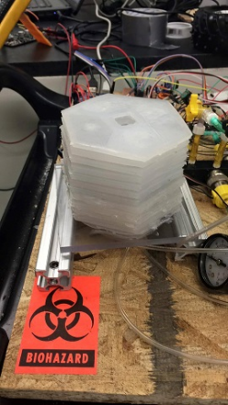
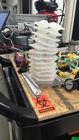
Once a few layers of the arm were created they were testing using a lab air supply to measure the inflation time, deflation time, and how much each layer would expand. An external air compressor was used to inflate each channel individually by manually opening the flow paths to each arm channel. The final number of layer was then determined based of the expansion size to allow for the desired reach. The necessary air pressure to operate the arms was also determined. In testing, it was discovered that the lower layers would expand to their maximum capacity before the upper layers would fully inflate. To compensate for this, the silicone thinner was only used in the upper layers since it reduced to strength of the material. Doing so allowed for a more uniform inflation of the arm. Directional control was also tested to ensure this method would work as intended.
Finger Testing
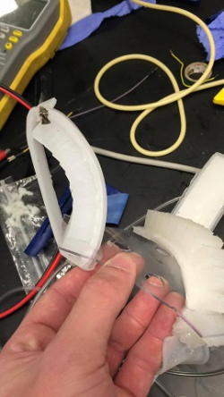
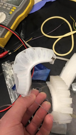
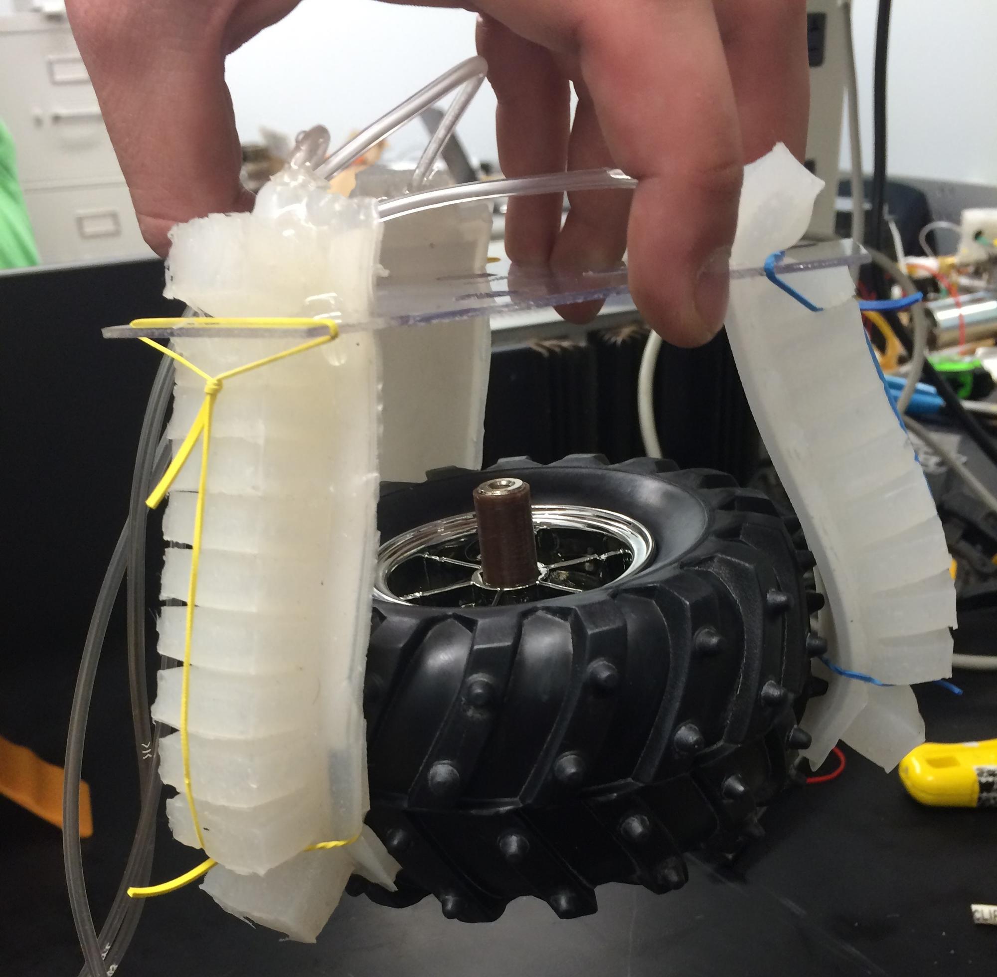
Testing using the external air compressor was also performed on the finger to determine inflation time, deflation time, and maximum pressure. It was also used to determine the strength of the fingers when inflated. Once of the tires was used as a test object to ensure the fingers were strong enough to grasp a tennis ball.
Air Flow System
Once built, the air flow system was tested using an external air compressor. First testing was done to find any leaks. Soapy water was applied to all connection to determine if air was leaking from the connection. Any holes found were sealed closed. Each solenoid valve was tested using a DC power supply to open and close them when under pressure. The compressor was also tested to determine how long it would take to inflate the tank. The compressor was able to pressurize the air tank to 100 psi in under 30 seconds. Each part of the system was also tested at incrementally higher pressure to determine all connection were stable, even when pressurized beyond what the expected pressure would be. The entire system was tested up to 100 psi. The pressure transducers put out an analog voltage based on the pressure. A correlation between applied pressure and output voltage was created to later be used in the controls.
Control System
The controls for the system was tested as the subsystem were combined. Initial testing was performed to ensure the output voltages from the Arduino were functioning properly when connected to the gaming controller. Once the power system was complete, the outputs from the power system were checked to ensure they were functioning properly. Once combined with the flow loop and navigation systems, the functions were continuously tested to work out any bugs.
Navigation System
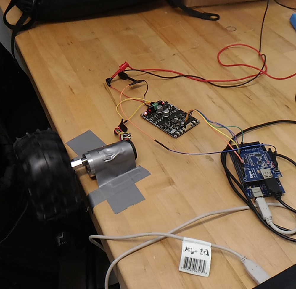
To test the navigation system, the motors were first hooked up to the driver board and the Arduino. Directional and speed control were tested to ensure proper functionality. Most testing on the navigation system occurred later once it was integrated into the rest of the system.
Power System
The circuit was first testing using Texas Instruments Webench design center. Once built the circuit was tested using a DC power supply and a multimeter to test the performance. Once integrated with the control, the MOSFET testing was also performed to ensure the functioned as required.
Integrated System Testing
Power and Control Systems
The power and control systems were integrated first since they work so closely with one another. A DC power supply was used to power the circuitry while testing. The gaming controller was operated while a multimeter was used to measure the output from the power board. Each function was tested and any issues were identified and corrected in this manner. Once it was confirmed that the controls were outputting the expected response, the power and control systems were integrated with the other subsystems.
Flow Loop, Power, and Controls
The power and controls were then integrated into the flow loop. The loop was pressurized using an external air compressor and then actuated using the various controls. Power loss testing was also performed to ensure the system would operate safely in the occurrence of sudden power loss. Since the tank was operating at much higher pressures than the arm or finger and the solenoid valves were normally open valves, it needed to be ensured that power loss would not cause the arm and fingers to rapidly inflate. To ensure this, the 4-way valve was setup so that in the even of a power loss, the arm and fingers would not be connected to the air tank. Instead both would release to the atmosphere. The next testing was performed to make use of the pressure transducers. The transducer were used as a feedback system to close off the solenoid valve if the pressure transducer reached a critical pressure. Doing so also allowed the pressure regulators to be used as a means of controlling the flow rate into the arm and fingers and the sensors to be used as a means of ensuring the arm and fingers weren't over-pressurized. The pressure transducer attached to the air tank was also used as a regulation system. Once the sensor reach 100psi, the compressor could be automatically turned off. Once it reach a minimum pressure it could also be turned on. Precautions were taken when programming the controls to ensure the arm and fingers could not be actuated when the compressor was running.
Object Manipulation Integration
Once the flow loop, controls, and power systems were combined, the object manipulation could also be integrated. Once the arm and fingers were mounted and the air tubes connected, the reach and strength of the arm was tested. An issue was found during testing in that the fingers made the arm top heavy and thus difficult to control. To overcome this, a 14 gauge solid copper wire was run down the center of the arm. The wire provided the added support needed to keep the arm upright when extended.
Final Testing
Once the navigation system was integrated, final testing was performed. This was done by simply operating all the controls as and determining the functionality of the robot. There were a few issues found during this final testing. The first issue was that the compressor would work once and then be on constantly even when not being controlled to do so. The issue found was that the high current spikes when turning the compressor on and off was burning out the MOSFETs and causing them to short. Even though the MOSFETs were rated for 60 amps and the compressor only drew 11 amps at a maximum, turning the compressor on and off caused large spikes that would cause the MOSFETs to fail. Multiple arrangements were tried with the same type of MOSFET but all results in the same failure. It was concluded that a stronger MOSFET capable of handling the current spikes was needed. In the mean time, the compressor was operated manually and the tank solenoid valve was reprogrammed so that it would open when the tank pressure transducer reached 100 psi. This allowed the group member to manually run the compressor until the tank valve opened and we then knew the tank was at 100 psi. Another issue was that the turning capabilities were very poor. The wheels were originally programmed so that only one would turn when the user wanted the robot to turn. Unfortunately, a single motor did not produce enough torque to do so. The motors were then reprogrammed so that one wheel would turn forward and the other backward in order to turn the robot. This still did not work though. This could very easily be fixed by using castor wheels in the back instead of a solid axle though. Since the primary focus of the project was the object manipulation system though, and not the navigation system, this was not of primary concern. The final product was exhibited at Imagine RIT. Some demonstrations can be seen below.