Miniature Soft Bending Actuator with Embedded Coiled Muscles
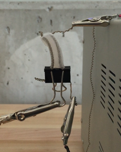
This project, inspired by PneuNets Bending Actuators from the Soft Robotics Toolkit, introduces a method of producing soft bending motion with simply and inexpensively produced components, simultaneously eliminating the constraints introduced by pneumatic elements. The goal is to produce actuation in a very small silicone part similar to that of PneuNets with voltage-driven artificial muscles, allowing power to be delivered by a battery rather than a bulky source of compressed gas.
In the Background section, we introduce the budding field of coiled-thread artificial muscles and some of the applications that have already been discovered. Additionally, we talk about PneuNets and their wide-ranging impact on the field of soft robotics, pointing out characteristics that excel as well as some that cause the technology to falter.
In the Design section, we describe our prototype for the silicone actuator, taking care to point out strengths as well as weaknesses, leading to envisioned next steps for improvement. In the Fabrication section, we give the materials and methods we used to produce the prototype, explaining the effects of variations in the two on performance.
We are the Zhao Research Group at Colorado State University, specializing in small-scale robotics with a focus on biomimicry. This project was worked on by David Trinko and Ali Abbas, with advising from Dr. Jianguo Zhao.
Background
The steadily growing field of soft robotics introduces the need to design entirely new components to replace those used in traditional, rigid robotic systems. One of the most immediate requirements is for innovative actuators that produce motion that is difficult or impossible to produce using standard components like motors, owing to the conceivably infinite number of degrees of freedom possible in soft systems.
The Whitesides Research Group at Harvard addressed the need for new actuation methods by developing PneuNets Bending Actuators [1], which are driven by pressurized fluid and are capable of widely varying types of motion depending on geometry and material. Actuators like these have properties that are heavily advantageous in robotics because of their extraordinary level of compliance, allowing interaction with objects of unknown geometry as well as safe interaction with humans; for example, one of the many demonstrations of this actuator involved grasping and lifting an egg without breaking it (see reference [1]).
However, pneumatic actuation introduces a multitude of constraints for application of the PneuNets technology. The Zhao Research Group, in working with small-scale robotics, cannot feasibly include the components required for PneuNets actuators (such as an air compressor and its power source) in the projects we work on; however, we saw the clear benefits of using actuators with similar characteristics to PneuNets in our systems.
We turned to another emerging technology, introduced in 2014 by Ray Baughman's group at the University of Texas at Dallas, [2] which is an artificial muscle that can be fabricated by coiling commercially available, inexpensive threads. Thermal expansion of the thread in its coiled state results in linear extension or contraction, depending on chirality, and can produce a force per weight superior to that of human muscle. Choice of an electrically conductive thread permits actuation by applying a voltage across the muscle, where Joule heating in the thread provides the driving force for thermal expansion.
Our idea was to combine the two technologies--PneuNets and the coiled-thread artificial muscle--to produce a soft actuator free from dependence on pneumatics. This allows the actuator to be used in systems in which weight reduction is critical (especially small robotic systems), where pneumatic components are not feasible or desired. Embedding the coiled muscles in a soft elastomer allows actuation similar to that of PneuNets simply by applying a voltage, with simpler and less expensive fabrication than what PneuNets require.
References:
[1] F. Ilievski, A. D. Mazzeo, R. F. Shepherd, X. Chen, and G. M. Whitesides, “Soft Robotics for Chemists,” Angew. Chem. Int. Ed., vol. 50, no. 8, pp. 1890–1895, 2011.
[2] R. H. Baughman et al. "Artificial Muscles from Fishing Line and Sewing Thread." Science 343.6173 (2014): 868-72. Web.
Design
The final iteration of the manipulator is a small rectangular piece of soft silicone with two extending nylon thread artificial muscles embedded symmetrically about its centerline. Upon application of a high enough voltage to one of the muscles, the muscle's extending motion strains the silicone and causes the manipulator to bend. Since the motion is a result of thermal expansion within the muscles and is driven by Joule heating, the degree of bending is related to the magnitude of voltage applied as well as the time during which it is applied, with higher voltages causing the manipulator to bend more quickly and longer times increasing the total deformation.
To gauge the success of the manipulator, its performance was to be compared to that of the PneuNets actuators. The goal was to produce a repeatable bending deformation qualitatively similar to what the pneumatically driven actuators had demonstrated. Unsuccessful iterations of the manipulator generally failed because the muscles burned out during testing; early on, the muscle would burn out before adequate deformation was achieved, but later, burnout would occur as a result of successive attempts to repeat the adequate bending motion.
Though nylon thread artificial muscles are capable of a superior strength-to-weight ratio to human muscles, the muscles used in the manipulator are so thin that the stiffness of even the softest available silicone is difficult to overcome. As a result, the final manipulator has dimensions much smaller than what was originally conceived. Additionally, the danger of burnout introduces an important constraint for the manipulator: a voltage cannot be applied for much time without allowing the muscle to cool, potentially complicating control. For example, to hold the manipulator in a certain degree of bending for a long time, a controller would have to cycle between on and off at some frequency to avoid overheating.
The iterative design process generally reflects a steady series of attempts to increase muscle strength while at the same time reducing total manipulator stiffness. Having met the original goal, future considerations tend toward conception of applications for demonstration of the manipulator's capabilities, such as robots that exhibit crawling or slithering motions.
Iterations in Mold Design
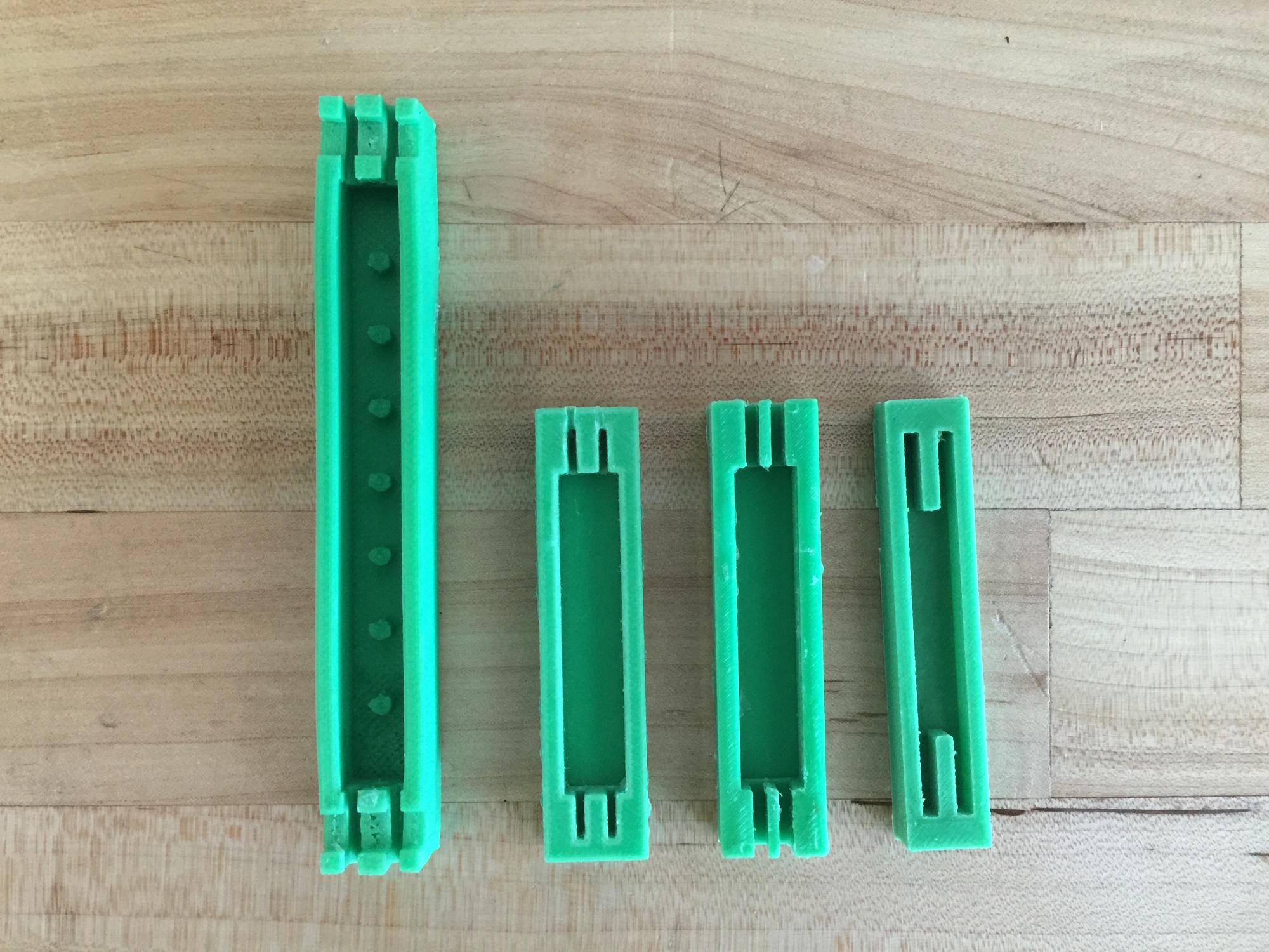
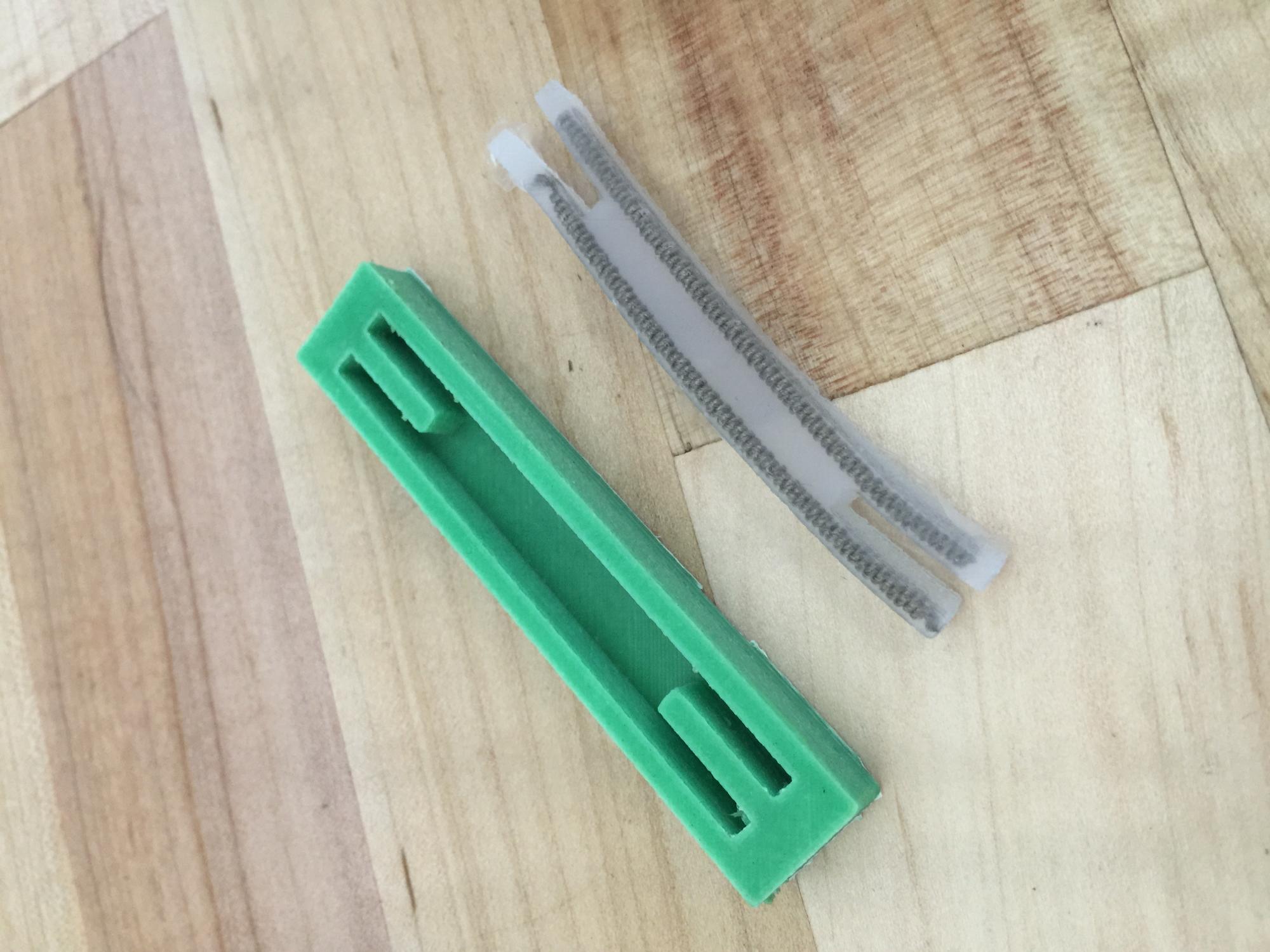
As can be seen above, all four mold designs have several properties in common: a rectangular shaped mold with a smaller rectangular cavity in one face and thin channels at the ends for constraining the embedded muscles and reducing leakage of silicone during curing.
The first mold to be designed and 3D printed produced a manipulator with dramatically greater dimensions than any successive mold: it had a length of 10 cm and a square cross section of 1 cm on each side. The mold also included short posts along its centerline to support a compression spring in the center of the manipulator, which was originally thought to be necessary to return the manipulator to a neutral position.
It was soon realized that not only would the elastic properties of the silicone be more than enough to return to a neutral position, but also that muscles on the scale we had imagined would not be sufficient to power a manipulator 10 cm long. The next two iterations heavily reduced the length and the depth of the mold (5 cm by 1 cm by 0.6 cm), and other alterations were related to changes in muscle design, discussed in the next section.
The final mold reflects a newfound understanding that the body of the manipulator should be as small as feasible (3.5 cm by 0.8 cm by 0.6 cm) and the muscles should be embedded as close to the edge of the manipulator as possible. For the first time, the channels at the end are flush with the edges of the manipulator, allowing for maximum leverage from the muscles. Lengthening the channels while closing the ends facilitates muscle placement and completely prevents leakage of silicone during curing.
Iterations in Muscle Design
For the artificial muscles we used, the chirality of the coils decides whether the muscle extends or contracts. When the coils in the thread twist in the same direction as the fibers of the thread, the muscle contracts; this is easily obtained and produces a strong muscle, as this type of coil forms naturally when the thread is twisted under tension. We initially planned to use this type of muscle, but we soon realized it would not be possible: in order to embed in the manipulator so that it would contract under applied current, a certain amount of pretension was required. It was found that, with two muscles across from one another, the force generated by one muscle could not overcome the pretension of the other muscle without burning out, and therefore, the manipulator could not bend.
Instead, we chose to use extending muscles, which have coils that twist in the opposite direction of the twist in the fibers of the thread. These require manually wrapping the thread around a mandrel, or a very thin rod. This introduces an immediate disadvantage: as the diameter of coils increases, the force produced by the muscle decreases, and the smallest diameter we could obtain with the extending muscle was more than twice that of the contracting muscle. However, use of extending muscles eliminates the need for a pre-applied force in the silicone, and as a result, one muscle provides only negligible resistance to the extension of the other.
Still, muscles made with a single thread could not produce enough force to drive a manipulator into more than a small bend. First, we attempted embedding two separate muscles in each side of the manipulator, but as-yet-unavoidable variations between muscles caused irregular motion that we could not envision properly controlling.
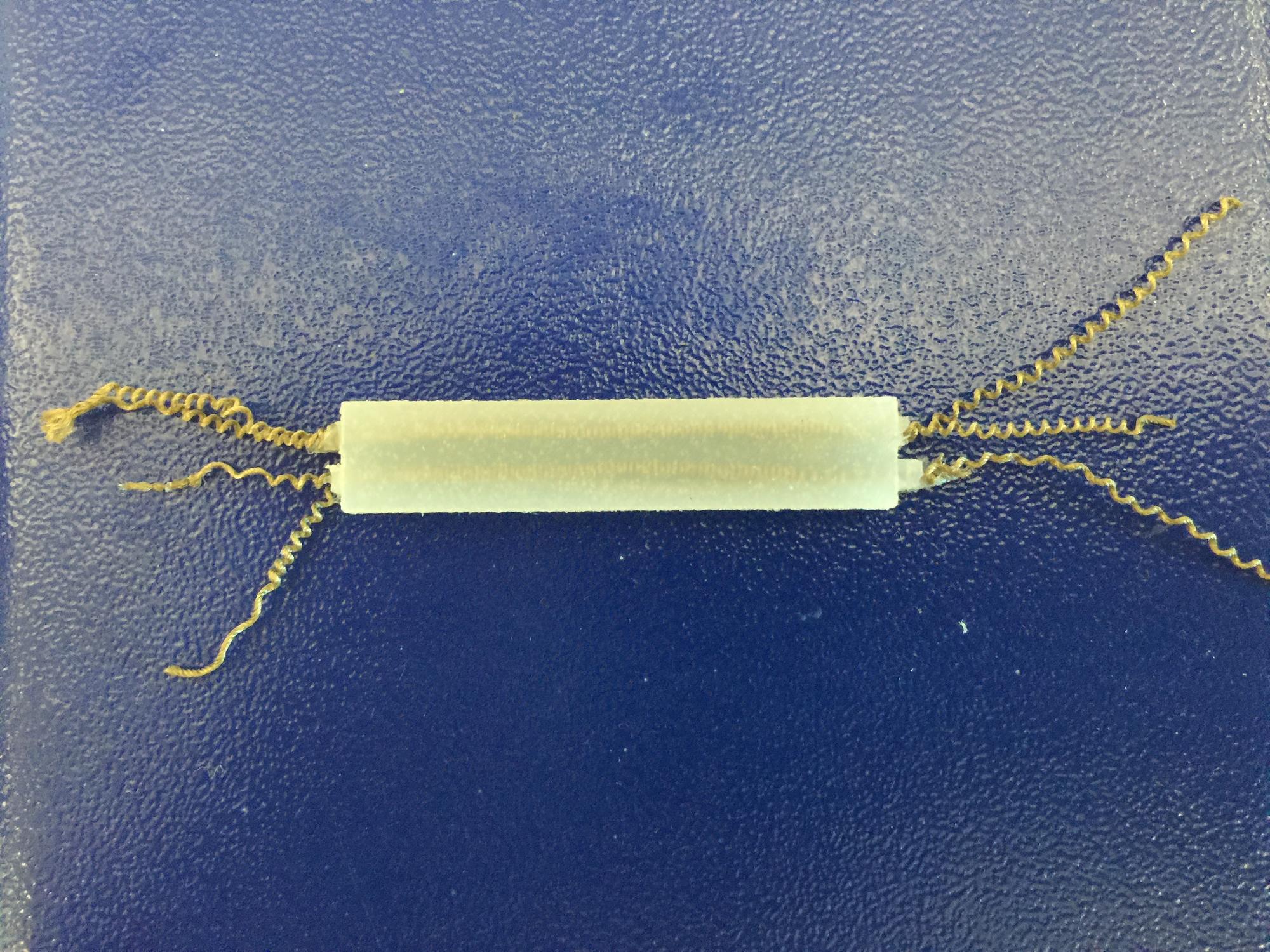
It was finally decided to produce a single muscle with two threads, effectively doubling the cross-sectional area of the muscle. These muscles, while more difficult to produce, are much stronger than single-thread muscles without introducing any uncontrollable irregularities in motion, and are what appear in the final iteration of the manipulator.
Strengths, Weaknesses, and Potential Modifications
The major advantages of this manipulator are related to cost and versatility: it is made of cheap materials (silicone and off-the-shelf thread) and can be powered with a small electric battery. In contrast, similar actuators that can be powered electrically use more expensive materials (e.g. shape memory alloys); and on the other end, the other lowest-cost way of producing this type of motion requires compressed air as a power source (e.g. PneuNets). Significantly, it is much more difficult to produce a pneumatic part on a similarly small scale, while the manipulator we have developed can still be scaled down.
However, this manipulator certainly falls short in certain areas. Even with the final prototype we developed, the danger remains of burning out the muscles if current runs for too much time, which limits its range of motion. Additionally, a relatively high current is required to produce significant motion (around 1 or 2 amperes) which may exceed the capabilities of a chosen battery.
Moving forward, the goal is to produce increasingly complex systems to demonstrate specific capabilities of the technology, including methods of sensing and control. This may involve embedding a greater number of muscles in a similar manipulator to diversify its range of motion, or possibly developing a fully functional robot based on the manipulator's technology.
Fabrication
Fabrication of the manipulator occurs in three distinct steps, each detailed in one of the following pages:
1. Design and 3D print the mold for the manipulator
2. Coil and anneal the artificial muscles
3. Pour the mold and embed the muscles
The required materials are listed below:
- Ecoflex™ 00-10 silicone, parts A and B
- Silver-coated nylon thread, at least 2 m length
- 12V DC motor
- DC power supply (capable of at least 12V and 2A)
- Brass weights
- Metal clamp stand (shown in muscle coiling section)
- Binder clips (at least 4)
- Thin carbon fiber rods, no larger than 1 mm in diameter
- Oven capable of 150°C
- ABS plastic filament and access to 3D printing
- Measuring cup and mixing tools (such as spoons)
- Various common tools (can be helpful: e.g. a flathead screwdriver for removal from mold)
Mold Design and Printing
Before fabrication can begin, a mold must be created. The easiest way is by designing a mold using CAD software and 3D printing it.
Due to the relative weakness of the artificial muscles that are used, the scale of this actuator must be small. For example, the final mold we designed produces a rectangular manipulator that is 35 mm in length, 8 mm in width, and 6 mm in depth. This permits the manipulator to execute noticeable bending when a voltage is applied.
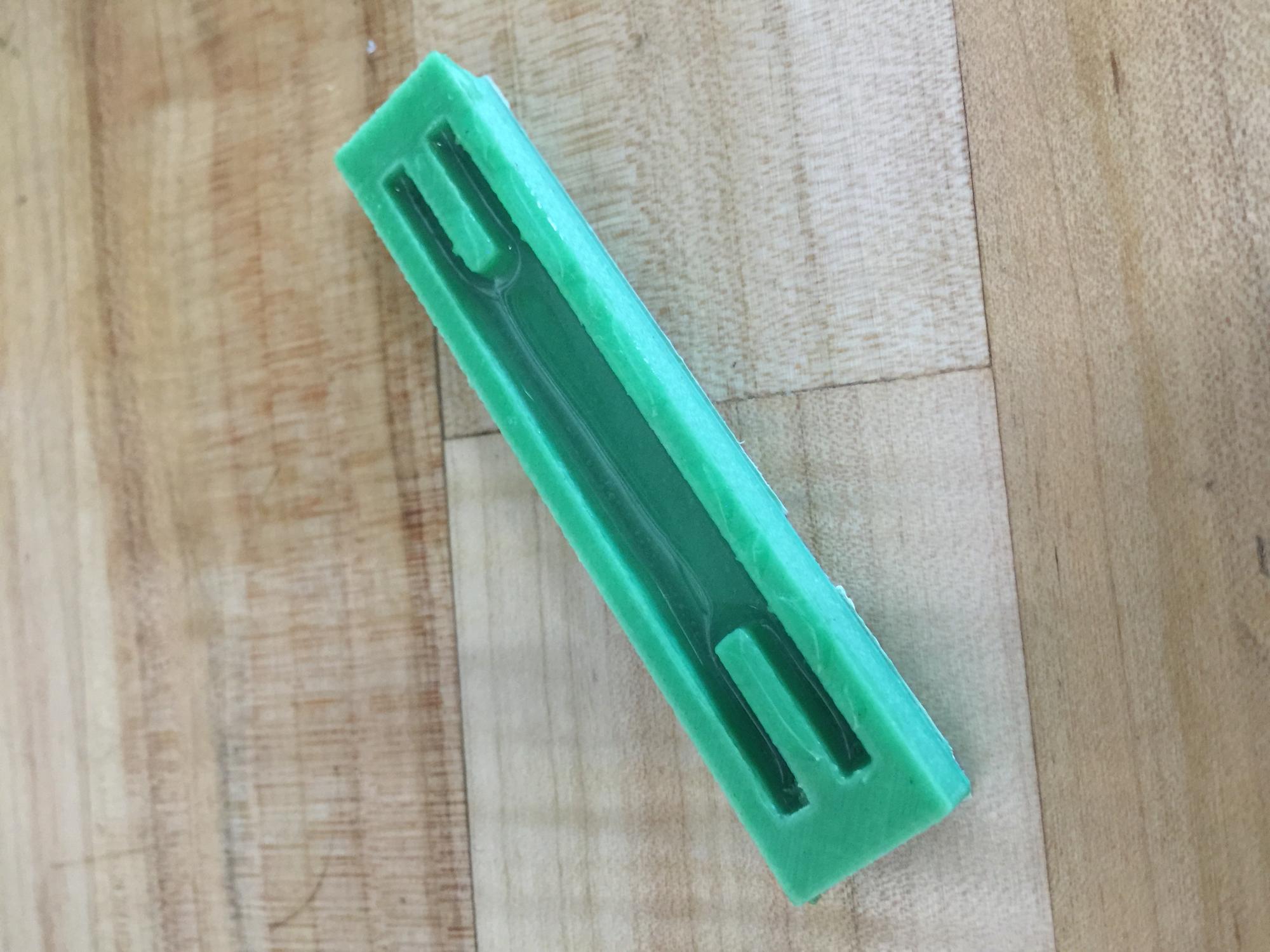
At its simplest, the mold should consist of a rectangular block with a rectangular cavity in one face that is the intended size of the manipulator (this is where the silicone is poured). One dimension of the manipulator should greatly exceed the other two, as in our design, where the length is almost four times the width.
Two narrow channels should be designed into each end of the mold, allowing the two artificial muscles to extend out of the mold during silicone pouring. The channel width should be at least 2 mm, and the channels should be symmetric about the centerline of the manipulator. To prevent leakage of silicone out the ends, the channels should be enclosed, as in the above image.
Since 3D printers and printing methods vary, we cannot give step-by-step instructions. It is important to use a printer capable of a resolution finer than the most detailed aspects of the design, and to avoid unnecessary features that will be difficult for the printer to replicate. We used ABS plastic filament and found its balance between rigidity and toughness suitable for this project.
Coiling of Artificial Muscles
Fabrication of the nylon thread-based artificial muscles requires a special apparatus, shown below. This includes a metal clamp stand, a DC power supply with alligator clip leads, a 12-volt DC motor, an oven capable of 150°C, brass weights, binder clips, Teflon nonstick spray, and thin cylindrical carbon fiber rods (no larger than 1 mm in diameter), in addition to conductive (we used silver-coated) nylon thread. Thread size can vary, with thicker thread producing muscles with greater strength; we used thread about 0.5 mm thick.
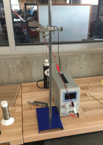
Muscle coiling apparatus
The motor, clamped at the top of the metal stand, should have a hole drilled through the side of its shaft, such that two threads can be run through and tied to secure them (see below), and a second hole drilled to a depth of about 5 mm into the end of the shaft, with sufficient diameter to insert a carbon fiber rod. At this stage, the motor’s shaft should be vertical, pointing downward, with two lengths of thread (each approximately 0.4 meters) strung through the shaft and tied twice at the end. Tie a weight (or group of weights, depending on the thread gauge; we used 135 grams) to the bottom of the lengths of thread, and let the system hang free. Using your hands or some other means, you must ensure that the weight at the bottom does not rotate during the next several steps; to accomplish this, we used wire to link the weight to one of the legs of the table without fully restraining vertical motion.
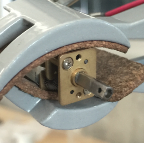
Motor for coiling apparatus clamped into stand. Holes have been drilled in the end and side.
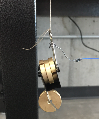
Weights tied to end of thread for coiling
Preheat the oven to 150°C and carefully coat two 15 cm lengths of carbon fiber rod with Teflon spray (important for facilitation of muscle removal later). Ensure that the power supply is set to provide 7 V, direct current. With the power supply off, attach the leads to the motor and then turn the power supply on, causing the motor to spin. To permit twist in the thread, ensure that the weight at the bottom does not rotate. Keep the motor running until coils just begin to form at the top or bottom of the thread, and then stop the motor, still making sure that the weight is not allowed to spin.
Now, rotate the clamp of the stand so that the motor's shaft is pointed just a few degrees above horizontal with the thread still hanging off the end and with the weight’s rotation prevented. Insert one of the carbon fiber rods that was Teflon coated into the end of the shaft, such that its long axis and the axis of rotation of the motor coincide. Reverse the leads to the motor and set the power supply to 1.5 V, which will cause the motor to rotate in the opposite direction. Taking care to support the carbon fiber rod with your hands, and still restraining rotation of the weight, turn the power supply on.
The rotation of the motor will cause the thread to wrap around the rod. As the rod is thin and not very strong, you must provide steady support at a point very close to where the thread hangs off of the rod to prevent a fatal bending load from the weight. In supporting the rod this way, you additionally ensure that successive wraps around the rod are very close together; however, you must make sure that the thread never wraps around itself. The image below shows this process near completion.
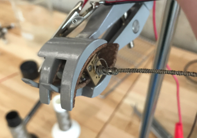
Thread wrapped several centimeters onto rod
Once wraps of thread cover a length of rod at least 1 cm greater than the length you designed for the manipulator, turn off the motor (still supporting the rod and preventing rotation of the weight). Use binder clips to pinch the thread at each end of the rod, and then cut the thread off from each end, freeing the weights and removing the rod from the motor. Repeat all of the above steps to produce a second muscle, and then place both rods with binder clips and thread still on in the oven for annealing.
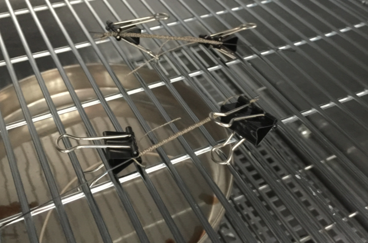
Two muscles annealing in oven
After one hour in the oven, carefully remove the rods. Allow them to cool completely, about 10 minutes, and then remove the binder clips and thread from the rod, making sure not to stretch out the coils. This may require using a pair of pliers to push the muscle off from one end. The final product of this stage is the coiled and annealed thread, which will be embedded in silicone (in the next section).
Muscle Embedding and Mold Pouring
From the previous section, you should have two extension muscles, each slightly longer than the designed manipulator. For this section, you need Ecoflex™ 00-10 (which comes as two jars of liquid, labeled parts A and B), and a container for mixing, alongside spoons or other mixing utensils.
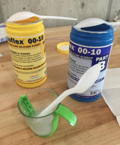
Ecoflex™ silicone and mixing container we used
Measure the radius of the muscles you fabricated as well as the depth of the mold. Before placing muscles into the mold, it is necessary to fill the mold to a certain level with silicone so that the muscles can be centered in the manipulator. Specifically, this level is one muscle-radius below the halfway point of the depth of the mold. Place a mark at this level using a pen or marker.
After stirring both parts of Ecoflex™ thoroughly in their jars (using separate stirring utensils), pour equal parts A and B into the mixing container, with at least enough to fill the mold (about 1 fluid ounce was plenty for ours). Stir this mixture (using another separate stirring utensil) for a full three minutes, taking care to scrape the sides and bottom several times during mixing. Carefully pour this mixture into the mold, up to the level previously specified. Allow this to cure; although the full four hours is not necessary, the silicone must be solid enough to prevent the muscles from sinking in.
Lay the muscles into the mold on top of the previously poured silicone so that they run parallel, each running through its own channel at the ends of the mold. Prepare another batch of silicone as done previously and pour it on top of the muscles until the mold is full. After the pour has settled, use a small instrument (like the carbon rod from before) to straighten out the muscles if they have developed curves during mold pouring, and additionally to ensure the top surface is level. Let the mold sit in room temperature.
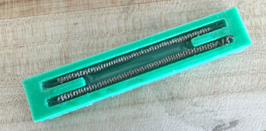
Mold with muscles laid in, prior to silicone pouring
After four hours, carefully pry the manipulator from the mold interior (a flat-head screwdriver may help).
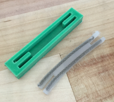
Finished manipulator, removed from mold
Finally, using a small pair of scissors, remove the silicone from the ends of the muscles (where the channels were), careful not to pull the muscles out of the manipulator body or cut the ends of the muscles off. This is only necessary to allow an attachment point for the power supply leads during testing.
Testing
At this stage in development, the crucial benchmark the manipulator had to meet was qualitative: it had to be able to repeatedly produce a bending motion similar to what has been demonstrated by the PneuNets actuators. Additionally, it needed to have the capability to bend in two opposite directions.
In early prototypes, the common failure mode was muscle burnout before sufficient bending had occurred, while later, failure would occur as a result of eventual overheating from attempts to repeat the bending motion too quickly after a previous bend. Below is a video of the final prototype's test.