Design
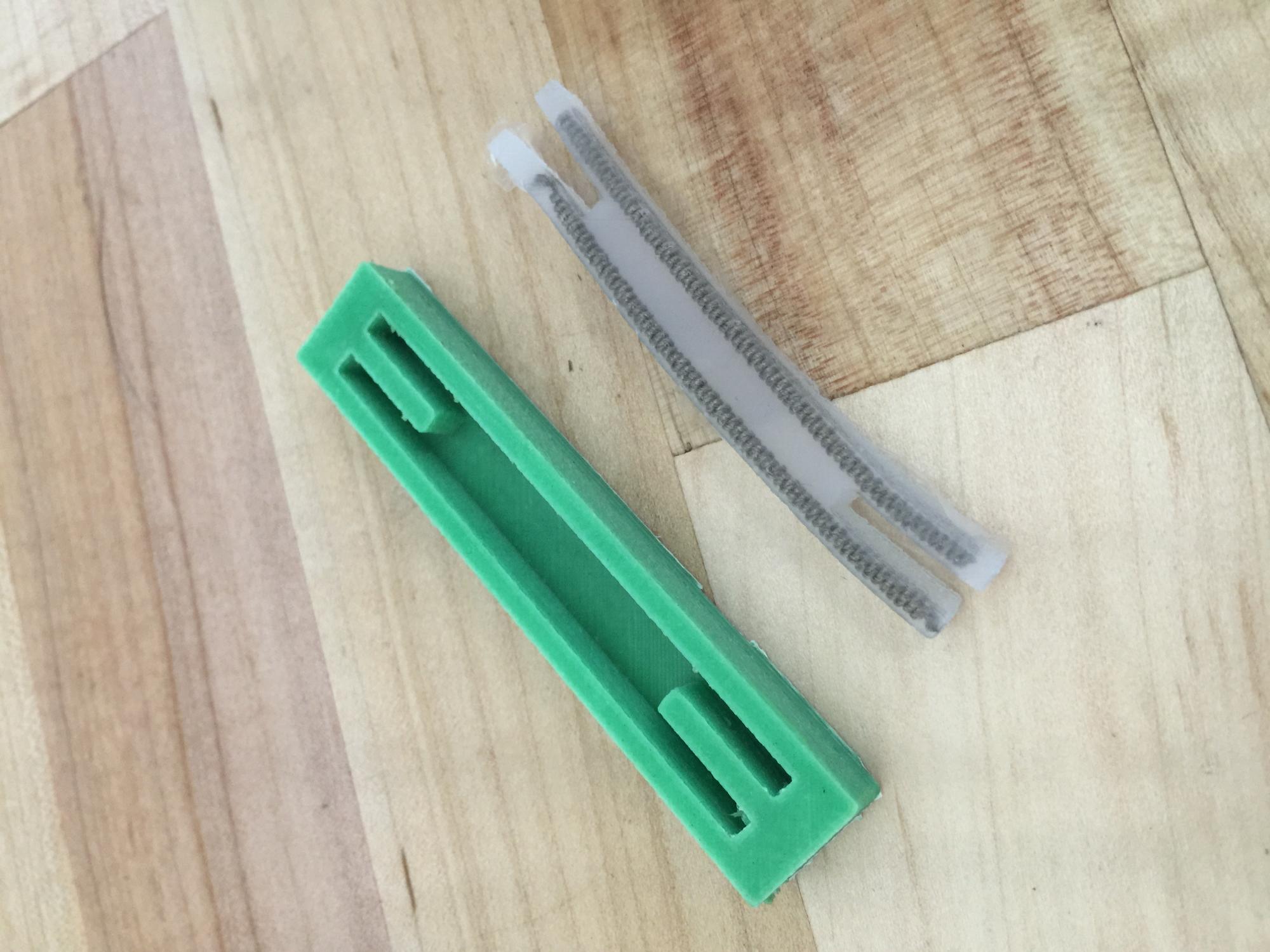
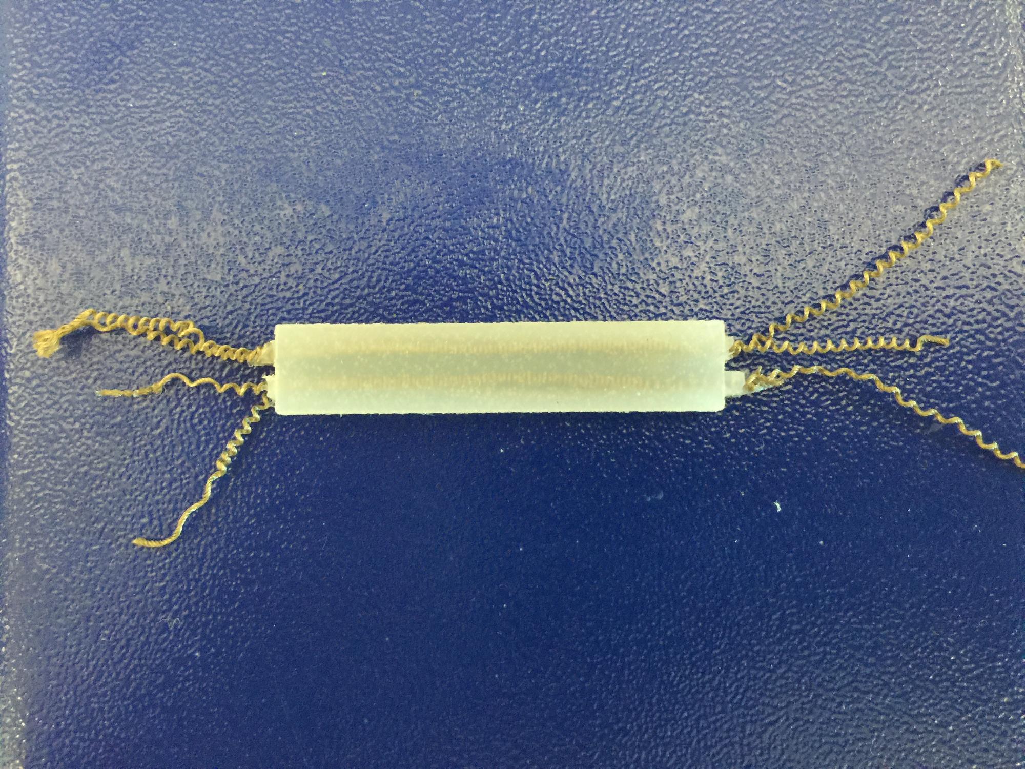
The final iteration of the manipulator is a small rectangular piece of soft silicone with two extending nylon thread artificial muscles embedded symmetrically about its centerline. Upon application of a high enough voltage to one of the muscles, the muscle's extending motion strains the silicone and causes the manipulator to bend. Since the motion is a result of thermal expansion within the muscles and is driven by Joule heating, the degree of bending is related to the magnitude of voltage applied as well as the time during which it is applied, with higher voltages causing the manipulator to bend more quickly and longer times increasing the total deformation.
To gauge the success of the manipulator, its performance was to be compared to that of the PneuNets actuators. The goal was to produce a repeatable bending deformation qualitatively similar to what the pneumatically driven actuators had demonstrated. Unsuccessful iterations of the manipulator generally failed because the muscles burned out during testing; early on, the muscle would burn out before adequate deformation was achieved, but later, burnout would occur as a result of successive attempts to repeat the adequate bending motion.
Though nylon thread artificial muscles are capable of a superior strength-to-weight ratio to human muscles, the muscles used in the manipulator are so thin that the stiffness of even the softest available silicone is difficult to overcome. As a result, the final manipulator has dimensions much smaller than what was originally conceived. Additionally, the danger of burnout introduces an important constraint for the manipulator: a voltage cannot be applied for much time without allowing the muscle to cool, potentially complicating control. For example, to hold the manipulator in a certain degree of bending for a long time, a controller would have to cycle between on and off at some frequency to avoid overheating.
The iterative design process generally reflects a steady series of attempts to increase muscle strength while at the same time reducing total manipulator stiffness. Having met the original goal, future considerations tend toward conception of applications for demonstration of the manipulator's capabilities, such as robots that exhibit crawling or slithering motions.

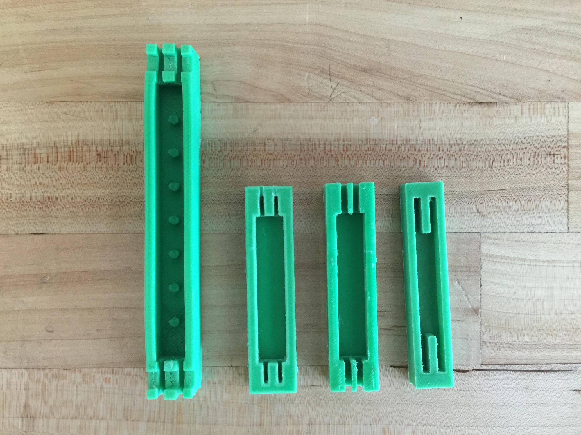
Iterations in Mold Design

As can be seen above, all four mold designs have several properties in common: a rectangular shaped mold with a smaller rectangular cavity in one face and thin channels at the ends for constraining the embedded muscles and reducing leakage of silicone during curing.
The first mold to be designed and 3D printed produced a manipulator with dramatically greater dimensions than any successive mold: it had a length of 10 cm and a square cross section of 1 cm on each side. The mold also included short posts along its centerline to support a compression spring in the center of the manipulator, which was originally thought to be necessary to return the manipulator to a neutral position.
It was soon realized that not only would the elastic properties of the silicone be more than enough to return to a neutral position, but also that muscles on the scale we had imagined would not be sufficient to power a manipulator 10 cm long. The next two iterations heavily reduced the length and the depth of the mold (5 cm by 1 cm by 0.6 cm), and other alterations were related to changes in muscle design, discussed in the next section.
The final mold reflects a newfound understanding that the body of the manipulator should be as small as feasible (3.5 cm by 0.8 cm by 0.6 cm) and the muscles should be embedded as close to the edge of the manipulator as possible. For the first time, the channels at the end are flush with the edges of the manipulator, allowing for maximum leverage from the muscles. Lengthening the channels while closing the ends facilitates muscle placement and completely prevents leakage of silicone during curing.
Iterations in Muscle Design
For the artificial muscles we used, the chirality of the coils decides whether the muscle extends or contracts. When the coils in the thread twist in the same direction as the fibers of the thread, the muscle contracts; this is easily obtained and produces a strong muscle, as this type of coil forms naturally when the thread is twisted under tension. We initially planned to use this type of muscle, but we soon realized it would not be possible: in order to embed in the manipulator so that it would contract under applied current, a certain amount of pretension was required. It was found that, with two muscles across from one another, the force generated by one muscle could not overcome the pretension of the other muscle without burning out, and therefore, the manipulator could not bend.
Instead, we chose to use extending muscles, which have coils that twist in the opposite direction of the twist in the fibers of the thread. These require manually wrapping the thread around a mandrel, or a very thin rod. This introduces an immediate disadvantage: as the diameter of coils increases, the force produced by the muscle decreases, and the smallest diameter we could obtain with the extending muscle was more than twice that of the contracting muscle. However, use of extending muscles eliminates the need for a pre-applied force in the silicone, and as a result, one muscle provides only negligible resistance to the extension of the other.
Still, muscles made with a single thread could not produce enough force to drive a manipulator into more than a small bend. First, we attempted embedding two separate muscles in each side of the manipulator, but as-yet-unavoidable variations between muscles caused irregular motion that we could not envision properly controlling.

It was finally decided to produce a single muscle with two threads, effectively doubling the cross-sectional area of the muscle. These muscles, while more difficult to produce, are much stronger than single-thread muscles without introducing any uncontrollable irregularities in motion, and are what appear in the final iteration of the manipulator.
Strengths, Weaknesses, and Potential Modifications
The major advantages of this manipulator are related to cost and versatility: it is made of cheap materials (silicone and off-the-shelf thread) and can be powered with a small electric battery. In contrast, similar actuators that can be powered electrically use more expensive materials (e.g. shape memory alloys); and on the other end, the other lowest-cost way of producing this type of motion requires compressed air as a power source (e.g. PneuNets). Significantly, it is much more difficult to produce a pneumatic part on a similarly small scale, while the manipulator we have developed can still be scaled down.
However, this manipulator certainly falls short in certain areas. Even with the final prototype we developed, the danger remains of burning out the muscles if current runs for too much time, which limits its range of motion. Additionally, a relatively high current is required to produce significant motion (around 1 or 2 amperes) which may exceed the capabilities of a chosen battery.
Moving forward, the goal is to produce increasingly complex systems to demonstrate specific capabilities of the technology, including methods of sensing and control. This may involve embedding a greater number of muscles in a similar manipulator to diversify its range of motion, or possibly developing a fully functional robot based on the manipulator's technology.