
We designed this actuator using the computer aided design (CAD) software Siemens NX. The following short tutorial shows how to design such a combustion driven actuator. Note that other CAD software (i.e. SolidWorks, Inventor, AutoCAD,…) can be used, but this tutorial is specifically for NX software. The main reason to use NX is its simplicity in creating free forms. This might be helpful especially if you want to design complex geometries. If you do not have access to NX, we encourage you to follow along through the guide to understand the design process in principle and even to attempt to replicate our design in your own software of choice. Downloads of the part files for the actuator design in this tutorial can be found here which include formats compatible with most CAD software.
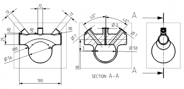
In the following sections, we show you how to create the simple combustion driven actuator shown below. All necessary sizes are indicated in the figure below. The design is comprised of a cylinder, which partially drives through a hollow sphere. Three channels, aligned at different angles towards the sphere center, form the gas inlet, exhaust and igniter electrode connection.
Again, all part files can be found here.