Designing the mold
Now that the actuator has been designed, we need to make the mold that will allow us to cast the part. To do this, we will "invert" the design from the previous steps. This inversion process essentially involves making a part that has the same shape, but with slightly larger dimensions in order to enclose the actuator design and then subtracting the actuator design to create a hollow mold. We then have to add filling and venting holes to allow silicone to enter and air to escape the mold during casting. This section will detail how to create the basic mold for the actuator designed in those previous steps.
Note: The minimum wall thickness of the mold should be 1.5 mm. Otherwise, your 3D printer might not be able to successfully print the mold. Also, the silicone filling becomes quiet difficult in terms of leaking spots.
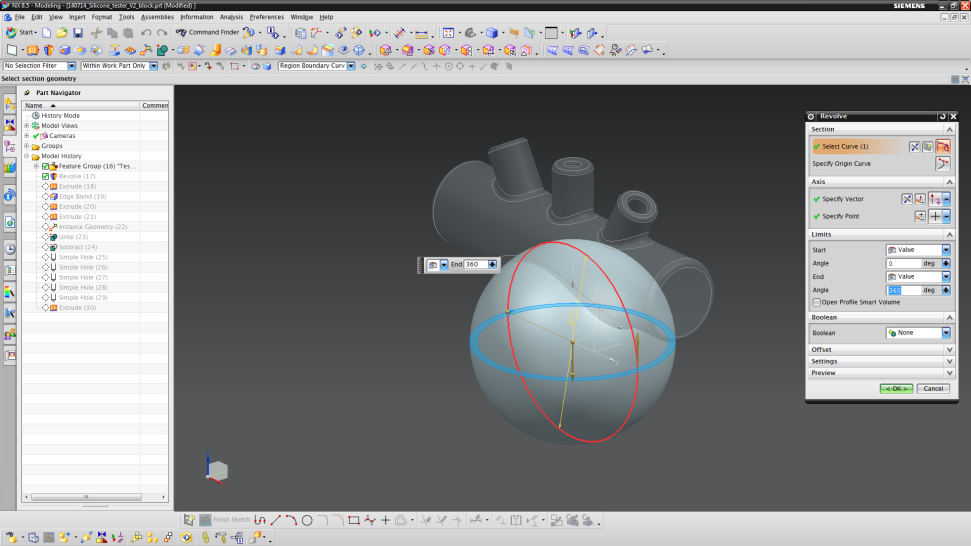
- Start by inserting a “Revolved” part (Insert → Design Feature → Revolve).
- Choose the ZX plane to draw the sketch.
- Sketch a circle with origin (0,0) and a diameter of 59 mm.
- Set the limits from 0° (start) to 360° (end).
- Next, add another “Extruded” part (Insert → Design Feature → Extrude).
- Choose the ZY-plane for your sketch and sketch a circle with origin (0,28) and a diameter of 28 mm.
- Unite the two parts by selecting the “Boolean”-setting to “Unite”.
- Like in Step 1, we now build the mold parts for the channels.
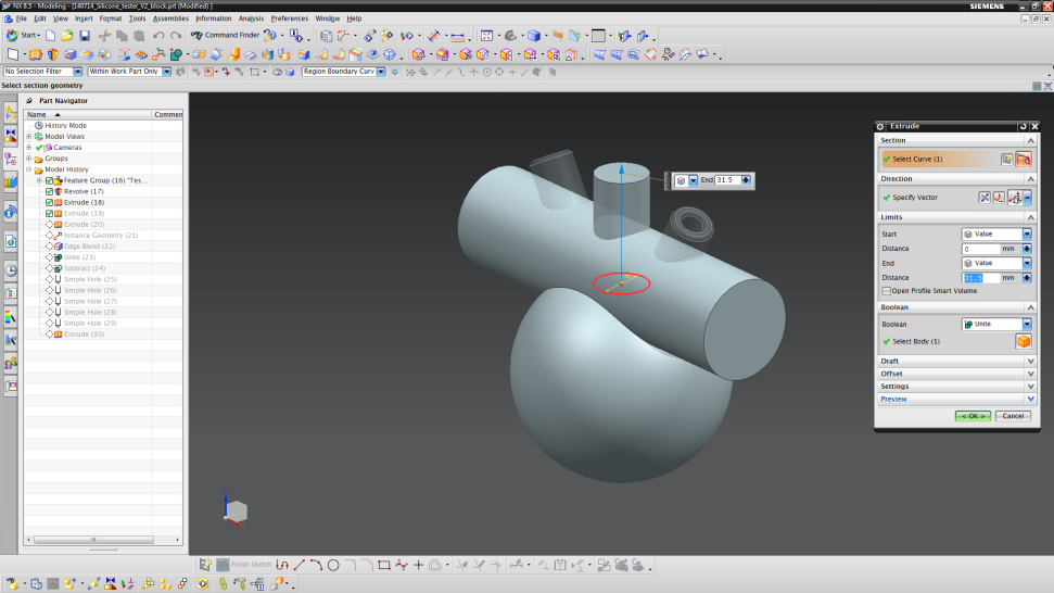
- Create an “Extruded”-part (Insert → Design Feature → Extrude) and set the sketch plane to the vertical orientation line (the sketch plane should face vertically) and draw a circle (origin (0,0), diameter 15 mm).
- Extrude the circle from 0 to 31.5 mm along the Z-axis.
- Unite the cylinder with the remaining parts by choosing “Unite” in the Boolean part.
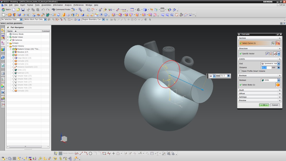
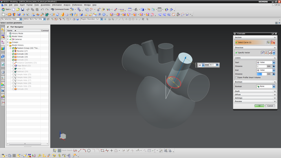
- For the sloped channels, extrude (Insert → Design Feature → Extrude) a cylinder from a circle sketched at origin (0,0) and a length of 36.5 mm along the sloped orientation line.
- Do not unite the cylinder with the remaining parts in the Boolean setting this time.
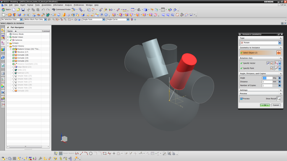
- Copy the cylinder as described in Step 1 (Angle = 180°, Number of Copies = 1).
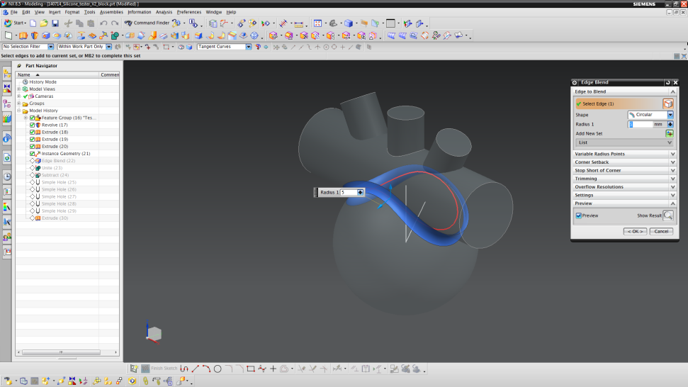
- Blend the connection of the sphere and horizontal cylinder as shown below. Choose an edge blend radius of 5 mm.
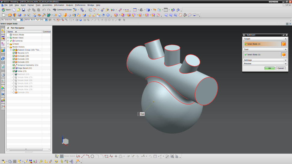
- Unite all mold parts designed in Step 3 using the “Unite” tool (do not include the actuator design from steps 1 and 2).
- Afterwards, subtract the actuator design from the mold to get the inverted design (Insert → Combine → Subtract).
Dead volumes
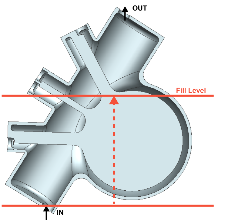
One of the main problems when creating and filling a mold are dead volumes. These dead volumes can trap air and therefore destroy your design upon filling uncured silicone. Hence, the design not only has to be “inverted” to form the mold but also specific connections (in the form of vented holes) to the outside have to be made. The vented holes enable the escape of air, in order to allow silicone to fill the pockets that would otherwise be filled with this trapped air. Our design needs four of these vents, which are all positioned at the end of a channel inlet.
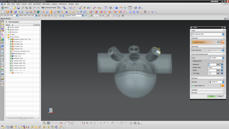
Add all necessary filling and vented holes by adding holes into the hollow mold
- We first make the holes that will be used to fill the mold with uncured silicone.
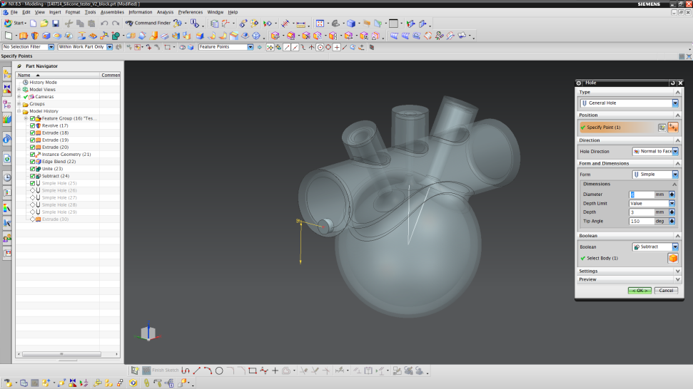
- Begin the process by inserting a hole (Insert → Design Feature → Hole).
- The first hole is set on one of the faces of the horizontal cylinder.
- The center of the hole should have coordinates of XC = 0 mm and YC = 18 mm.
- Specify a diameter of 6 mm, depth of 3 mm and a tip angle of 150°.
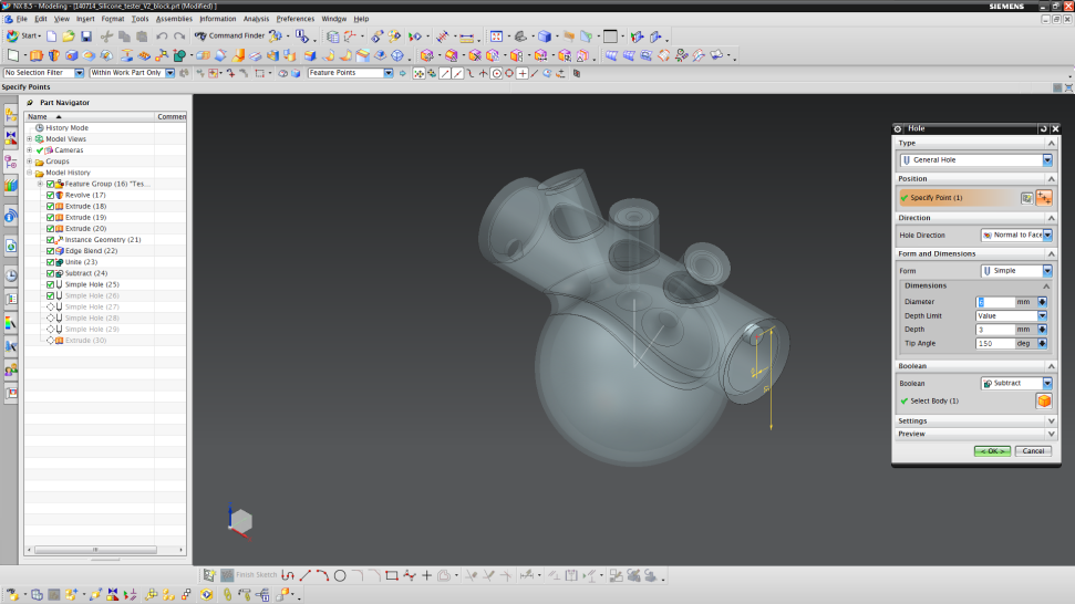
- The next hole will be on the opposite face of the horizontal cylinder.
- This time, the hole should be at XC = 0 mm and YC = 37 mm.
- Use the same hole dimensions as before.
- Now, we will make the vented holes.
- Insert another hole and choose to sketch on one channel top.
- The point should be at XC = -3.5 mm and YC = 0 mm.
- Use the same hole dimensions as for the horizontal cylinder.

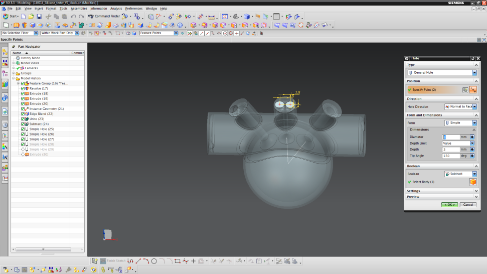
- For the vertical channel, we will make two holes.
- Insert another hole and choose to sketch on the top face of the middle channel.
- The two points have to be on the same horizontal line (XC1 = -3.5 mm / YC1 = 0 mm and XC2 = 3.5 mm / YC2 = 0 mm).
- Use the same dimensions as before.
- The last hole should be designed on the remaining channel top surface at the point XC = 3.5 and YC = 0 mm. Continue to use the same dimensions for the hole.
- Now, your mold should have an interior as shown in the beginning of Step 3.
- To see the cross section, press “Crtl + H” and choose the YC plane.