
This tutorial contains step-by-step instructions for making a solid model of a fiber-reinforced bending actuator mold in SolidWorks 2013. The SolidWorks part files can be downloaded here. If you prefer to use a different software package, you should be able to apply the general tutorial steps to most solid modeling environments.
Dimensions
The inner diameter of the actuator is defined by the steel rod used in the casting process. This tutorial and the associated part files assume that a 1/2" (12.7mm) diameter half-round rod will be used in the fabrication process.
The thickness of the actuator walls is defined by the difference between the rod diameter and the mold diameter. Here, we will create molds that will result in an actuator inner bladder with 2mm wall thickness.
Finally, the overall length of the actuator described here will be 170mm (6.7").
Of course, you can adjust these dimensions to suit your own design by modifying the relevant steps in the tutorial, or by editing the provided solid model files.
Overview
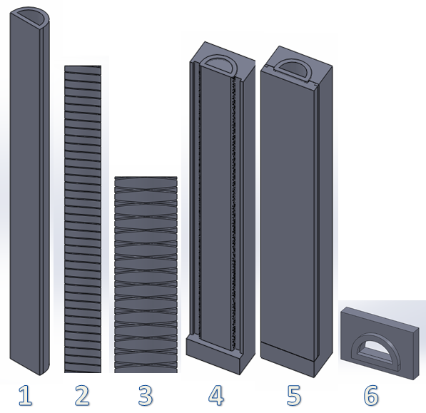
We will follow these steps to make our mold for the inner core of the actuator:
- Make the actuator body, an extruded semicircular tube (with filleted edges)
- Make one set of thread grooves with a swept cut. The sweep profile is a small circle, and the path is a helix.
- Mirror the swept cut to get the 2nd set of thread grooves.
- Make the main mold: create a base mold block, use an assembly to position the block relative to the actuator, then use the Cavity feature to subtract the actuator from the mold block.
- Repeat for the thin mold top, this time subtracting both the actuator and the main mold.
- Make the mold cap.
After making these molds, we can make the molds for the outer skin using the exact same process, even re-using the same solid model files:
- Make a copy of all the files in a new folder by opening the interim assembly for the top mold (which contains all the parts) and using File > Pack and Go. You should use the "Add Prefix" option to differentiate the new files. Do not just copy & paste files in Finder/Windows Explorer, as this will mess up your references!
- In the newly copied folder, open the actuator file. Get rid of the thread grooves by deleting the Mirror and Swept Cut features (check the "Also delete absorbed features" option to clean up the associated sketches).
- Increase the wall thickness by however thick you want the outer skin to be (1mm recommended). Just change the smart dimensions accordingly and rebuild the part.
- Open the interim assembly for the top mold, rebuild, and save. The main and top mold pieces will update themselves to fit the new actuator.
- If you feel that the top mold piece is too thin after the change, you can thicken the pieces. In the interim assembly, double click on the top mold. The smart dimensions will appear; double click the dimension corresponding to thickness and increase it. Next, double click on the bottom ledge of the main mold, and again modify the smart dimension so that the ledge width is increased by the same amount. Rebuild the assembly and save all the parts.
- The mold cap needs to be updated manually, but it is very easy: open the mold cap file, change the wall thickness smart dimensions in the sketch, and rebuild.
| SRT_FR Mold SolidWorks Files.zip | 17.95 MB |