
This section describes how to perform Finite Element Method (FEM) analysis of our PneuNet actuator using the Abaqus software suite. FEM allows us to model the behavior of the actuator and see the effects of changing various parameters such as material stiffness or chamber dimensions, without needing to refabricate and retest the actuator every time a design parameter is changed.
The Abaqus input file created in this tutorial can be downloaded here and the .STEP files of the actuator can be downloaded here.
Overview of model components
- A Fluid-Structure Interaction (FSI) problem treated with a standard/implicit FEM using Abaqus/CAE (SIMULIA, Dassault Systèmes)
- 2 materials:
- Elastosil M4601 silicone rubber: Yeoh strain energy potential defined by the coefficients C10 = 0.11, C20 = 0.02. Density of 1130 Kg/m³, assumed isotropic
- Paper: density of 750 Kg/m³, a Young’s Modulus of 6.5 GPa and a Poisson’s ratio of 0.2
- 2 sections:
- Elastosil (uniform solid), assigned to the main body and 2 bottom layers
- Paper (uniform shell), assigned to inextensible layer
- 2 loads:
- Gravity, with boundary condition as 1 end rigidly fixed (encastre)
- Pressure, acting at all internal faces of the actuator cavity
- Contact interaction between adjacent chamber walls
Overview of FEM steps
- Import parts
- Make surface placeholder for paper layer
- Assign material properties to the parts (create materials, assign materials to sections, assign sections to parts)
- Assemble parts
- Model paper layer as a skin and assign final section
- Create a surface on inner cavity faces
- Apply loads (gravity, and pressure on inner cavity) and set boundary conditions
- Add contact interaction
- Create mesh and run job
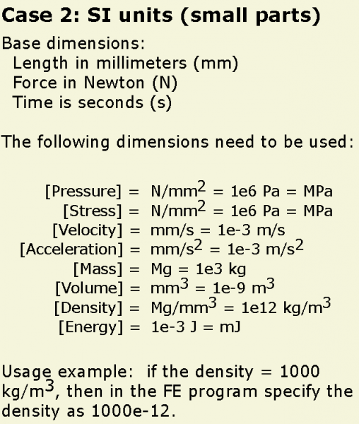
A note on units
Abaqus doesn’t interpret units so it is up to the user to make sure they are consistent. In this tutorial we use the following scheme:
| PneuNets Abaqus CAE input file | 2.73 MB | |
| Modified for Abaqus - PneuNet Molds .STEP Files (.zip) | 40 KB |