Mesh Network Setup
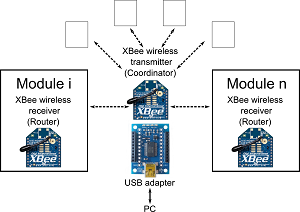
| The current selection of XBees allows the establishment of a mesh network which means a communication between multiple devices that are connected to an XBee. In XBee terms, this means that there is a single coordinator (transmitter) which can communicate with all the routers (receivers) within the same wireless network. In the Hot Glue Kit perspective, this means that the user can communicate with multiple actuation modules with a single XBee transmitter connected to a PC. The free software XCTU, allows users to configure their XBee components to define the network ID, router and coordinator roles and many other communication properties. |  |
|
There are multiple points that require attention due to the design choice of mesh networks with XBees.
|
|
Actuation Command Protocol
When the transmitter (coordinator) XBee is connected to a PC via USB, a serial connection needs to be established. Details about this connection can be found in the XBee and Arduino subsection. The communication with the module is very simple: the user sends text commands from the PC, and the module executes and responds. In order to increase the strength of the communication, we established a handshake protocol. This means that for every command user sends from the PC, the module has to answer with a proper respond so that the user can be sure that the command is received.
There are two main types of actuation control for Hot Glue Kit modules: direct mode and alternate mode. In direct mode, the user specifies the amount of turns for the DC motor to turn. As there is a position control implemented, the module will rotate the motor to the desired number of turns and it will stop. The other mode is the alternate mode, where the user specifies to target turn amounts and the motor will continuously alternate between these target values, which generates a oscillatory pull-release behavior. In the current setup users can only define the amplitude of this motion, not the frequency as there is only a motor position control implemented.
Users can also set phase timers if they want to set a phase difference between their modules. They simply command one module to wait a certain time before it starts executing the motor rotation command.
All the necessary commands and the module responses can be found here.
Motor Position Control
We implemented a simple PD controller for the motor position control in the modules, where:
Motorout = Kp (Poscurrent - Postarget) + Kd (Motorvelocity)
The proportional (Kp) and derivative (Kd) gains are manually tuned. The current motor position (Poscurrent) is read from the optical encoders while the target position (Postarget) is defined by the user as the target turn amount. The motor velocity (Motorvelocity) is calculated as the average of position change in the last 10 steps of the microcontroller loop. The output (Motorout ) is mapped to a proper PWM signal to be sent to the motor driver.
Load Control
Currently there are no additional sensors in the circuitry to detect the load on the tendon cable and the motor shaft. As an extensive load might damage the power circuitry, the motor driver and the battery, we implemented a coded load detection mechanism to release the motor when an overload is detected.
The optical encoders provide 12 counts per motor shaft revolution, and as the motor gear reduction rate is 100:1, this means that a complete motor turn should yield 1200 counts. When there is an overload, the motor stalls which means that it will not be able to rotate any more. By looking at the counts, we decide that there is an overload if (1) there is more than half a turn left until the target turn position and (2) the motor velocity is zero.
