Overview
 |
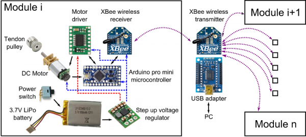
| We have come up with a functional set of electronic components for the Hot Glue Kit module box so that the users can perform untethered, long lasting, programmable, and strong actuation for their soft robots. The figure above shows the main overview of the electronics and control with the details of the box contents. A single module contains a 3.7V LiPo battery, a power switch, a 5V Step up regulator, a brushed DC gear motor, a pulley, a microcontroller, a motor driver and a wireless receiver unit. In addition to these, another wireless transmitter and a usb adapter are required to establish connection with a PC so that the user can send and receive messages to the actuation module. With such a setup, the user can control multiple actuation modules with a single transmitter. The details of how to control modules are given in the Control section. |
Battery and Power Distribution
We wanted our actuation module to be free of power cables so that the user can attach them on their robots and fully explore the interaction between the robot and the environment. Also long lasting operation was a necessity to get the best out of the robots. Therefore we have selected a 3.7V 980mAh rechargeable LiPo battery to power up the entire system. All the electronic components in the box require 3.7V to operate except for the DC motor which requires 5V for full speed operation. That is why 5V step up regulator is required to generate the necessary motor voltage. The figure above shows the logic circuit voltage line with blue and motor voltage line with red dashed lines. Within a continuous active motor operation a single battery can last up to 6 hours with this setup.
Motor and Motor Driver
In order to pull the tendons, we use a brushed DC gear motor with an extended shaft. This motor can pull up to 11N of load without stalling and rotate 320RPM freely. A magnetic encoder is placed on the extended shaft to provide motor shaft position information in order to establish a feedback loop for a motor position control strategy. To control the DC motor within a feedback loop, we selected a sufficient motor driver unit which receives commands from the microcontroller. This design gives us the ability to control our motor like a servo motor, but with higher torque output and endless revolutions.
Wireless Communication
Another important design choice was to enable programmable actuation as users will need to change their actuation depending on their robot designs. That is why we used an XBee S2 modules for wireless communication between the actuation modules and the user. With a single XBee transmitter that is connected to a PC with a USB adapter, users can send commands to single or multiple modules which contain an XBee receiver each. This allows the instant control of multiple modules with a single command, however it should be noted that XBees can be interfered with all the radio signals which might slow down the communication speed. A deeper insight is given in the control section about wireless communication with XBees.
Microcontroller
In order to receive commands from the user, collect motor position from the encoders and drive the motors accordingly, we used a 3.3V 8MHz Arduino Pro Mini microcontroller.
