Textile Silicone Hybrid Sensor
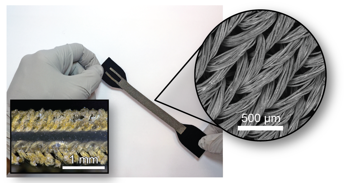
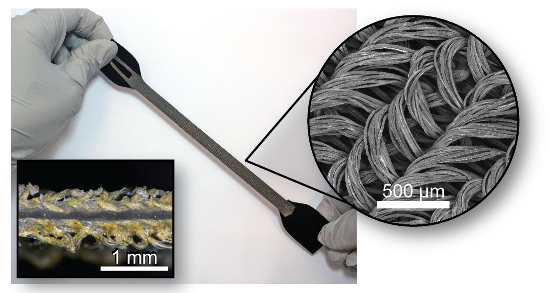
Textile Silicone Hybrid Sensors (A. Atalay et al. 2017) are highly stretchable capacitive sensors, made up of three layers; two outer electrode layers of highly stretchable silver plated knitted textile that surround a dielectric layer of silicone elastomer. When the electrode area and the dielectric thickness change in response to applied strain, a capacitance change occurs. Consequently, measuring the change in capacitance can be used to determine the magnitude of an applied strain.
|
|
The sensor is designed to address the limitations of traditional capacitive soft sensors by utilizing a hybrid approach combining silicone and textiles to create a composite with favorable mechanical properties. Additionally, a process for creating robust hard-to-soft connection for these sensors with micro coaxial cable secured to the electrode layers is discussed within the fabrication section.
|
Soft sensors are well suited for continuous monitoring of body movements, human-machine interfaces and for measuring physiological parameters of the human body when compared to their traditional more rigid counterparts. The Textile Silicone Hybrid Sensor is capable of enduring repeated dynamic strain with fast response times, making it specifically well suited in human articulation detection, soft robot applications and exoskeletons. In these applications, sensors need to be able to obtain accurate measurements close to the human body in a comfortable manner and that is straightforward to integrate into wearable garments. A case study of this application is detailed in the Case Study page.
This documentation set contains files and instructions detailing the design, fabrication and testing of a specific Textile Silicone Hybrid Sensor. This process can be customized to diverse applications by creating variations in material, size and construction.
| Some of the information contained in this web site includes intellectual property covered by both issued and pending patent applications. It is intended solely for research, educational and scholarly purposes by not-for-profit research organizations. If you have interest in specific technologies for commercial applications, please contact us here. |
Design
The Textile Silicone Hybrid Sensor is a capacitive sensor. When the electrode area and the dielectric thickness change in response to applied strain, a capacitance change occurs. Consequently, measuring the change in capacitance can be used to determine the magnitude of an applied strain. A further discussion of the working principle can be found in Step 5 of the Fabrication Section.
|
The electrode layers are knit fabric made from silver coated nylon/spandex blend yarns giving the fabric conductive properties. The dielectric layer is a silicone elastomer that exhibits high stretchability (up to 900%) and low viscosity, allowing easy penetration into fabric micro structures. The soft sensor is also pliable for comfortable applications on the human body as well as strong enough and robust for repeated wear and tear.
Manufacturing Method
To create the most repeatable sensor this documentation set uses a scale-able batch manufacturing process, which can produce a more accurate, robust, sensitive, and repeatable sensor. By fabricating in bulk, the process allowed for almost identical sensors with consistent baseline capacitance values to be produced. For example five such sensors cut from the same larger mat had 174 pF ± 1.41 as values for their initial capacitance. This process produces large sensor mats that can then be cut into size as determined by the application; for example, a small linear sensor for a pinky finger and a large curved sensor at the hip. A more detailed process for producing this sensors is described in the Fabrication Section of this documentation set.
|
Variations in Construction
The sensor created in this documentation set is made using Ecoflex 00-30 and a MedTex 130 silver conductive knit spandex, however these materials are not the only ones that can use to create hybrid sensors. Substituting the Ecoflex for a harder silicone will create a stiffer yet fully functional sensor while substituting for a more softer silicone will result in a more flexible sensor. This sensor described here has a reliable working range up to 100% strain but if your application requires larger strains a conductive knit fabric with higher stretch properties can be used. No matter your sensor construction you will have to calibrate your sensor to understand its specific force-strain relationship.
Additional layers can be added to make the sensor more robust in environments where it may be subject to increased electrical interference. Simply adding an extra layer of conductive fabric for shielding will reduce the amount of EM interference and fringe fields from anything conductive (including biological entities).
The sensor may also be completely encapsulated within silicone elastomer to modify its mechanical properties and provide hermetic sealing for aquaus environment applications as seen in the figures below.

|

|
Fabrication

|
The Textile Silicone Hybrid Sensors are made of two conductive knit fabric electrode layers surrounding a dielectric layer of silicone elastomer. The sensor layers are constructed using a batch manufacturing process described in the subsequent pages. An automatic film applicator is used to create a thin layer of elastomer and a fabric sheet is bonded to the top surface. After curing, the unfinished sensor is flipped over and the process is repeated on the other side. This process is able to create sheets of sensor mats as large as the film applicator used. The mats can then be cut into arbitrary, customizable, individual sensors. This method of batch manufacturing creates sensors with nearly identical performance in a repeatable and controllable way that is scaleable for rapid, robust, and reliable production of large sensor sheets.
|
|
Overview of Steps

|
Using a film applicator cast a sheet of elastomer that will become the dielectric layer of the sensor. |

|
Pour and cast another layer onto the dielectric. This will act as an adhesive layer. |

|
Lay fabric electrode layer on top and roll to flatten the fabric. Cure this layer of the sensor. |

|
After curing peel the unfinished sensor off of the tray. |

|
Flip the unfinished sensor over to face the silicone side up. Secure with masking tape. |

|
Cast onto the second side of the silicone using another batch of elastomer. |

|
Place the second piece of fabric and cure completely. |
|
|
Peel the sensor from the tray. |

|
Sensor Mat is finished! |
Bill of Materials
This section will give a list of items that are used in this project with selected links to suppliers.
You can download a detailed Bill of Materials here.
Note: Many of the items listed are just examples and you can use your own discretion to substitute parts which are easier or cheaper to obtain.
Elastomer layers

|

|

|
| Ecoflex 00-30 2-part silicone rubber | Mixing cups | Mixing sticks |
Tools and Equipment

|

|

|
| Lab gloves | Centrifugal mixer | Lab oven |

|

|

|
| Mass scale | Film applicator | LCR Meter |

|

|
|
| Laser Cutter | Iron |
Other Materials

|

|

|
| Masking tape | Conductive fabric Med-tex 130 | Fabric scissors |

|

|

|
| Roller | Loctite 416 | 0.3mm Micro coaxial cable |

|

|
|
| Thermal seam tape Bemis 3914 Sewfree | Acrylic sheet (large enough to fit sensor) |
| textile_silicone_hybrid_sensor_bill_of_materials.xlsx | 13 KB |
Step 1: Cast first side of sensor
Casting First Side

|
Cut two equally sized pieces of conductive fabric. These will become the electrodes on the outside of the sensor. The size of these pieces is dependent on the size of the desired sensor sheet and must also be cut along the wales as shown. Take note of the 'shiny' side of the conductive material as it will need to be placed facing away from dielectric layer. | |

|
Cut along the wales of the knit to keep the fabric's alignment as straight as possible for laser cutting. | |
|
|
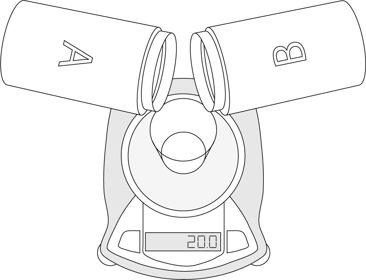
Measure and mix 20 grams of the elastomer parts A and B. You can use a centrifugal mixer to do this or simply by hand with a mixing stick. | |
|
|
Using the acrylic sheet as a tray, allow the film applicator to spread the elastomer mixture across the length of the tray. [Note: The elastomer layers will have colored dyes to help them stand out, it is not necessary to the sensor's construction]. This layer must cure completely. Cure in an oven at 70°C for 10 minutes. Without an curing oven it is best to have this layer cure overnight. | |
|
|
Using the same amount of elastomer (20 grams) cast a layer over the dielectric that will act as an adhesive between the fabric and the dielectric. | |
|
|
Lay one piece of fabric onto the silicone adhesive layer. Use a roller to apply pressure and adhere fully. This prevent delamination with repeated strain. Cure at 70°C for 10 minutes. | |
Step 2: Flip and cast second side
Once the adhesive layer for the first fabric side has been fully cured, the sensor will need to be flipped over and the last fabric layer will be adhered to the sensor. It is critical that the sensor be flipped carefully and laid down without any wrinkles or folds.
|
|
Slowly peel fabric and silicone from the acrylic sheet from the tray and flip. The elastomer side should now face up. Secure the layers to the acrylic tray with masking tape. |
|
Measure and mix another 20 grams of the elastomer parts A and B for the next layer. |
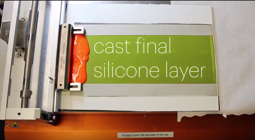
|
Use the film applicator to cast the final layer of silicone from 20 grams of the elastomer. |
|
|
Place the second layer of fabric on top and use the roller to apply even pressure to adhere the layer. Cure at 70°C for 10 minutes. |
|
The sensor mat is now complete and individual sensors can be cut out of it. |
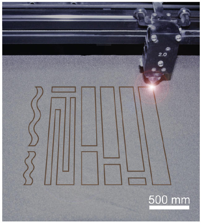
Step 3: Cut sensors out of batch mat
A laser cutter can be used to cut the sensor mat into multiple sensors. The mat must be laminated with masking tape to prevent it from burning during the laser cutting process. The following table shows the power settings used for this construction method for the United Laser Systems: VLS 6.60 laser cutter brand. These settings may vary if the sensor's construction is altered.
United Laser Systems: VLS 6.60 |
|
| Power Settings: |
50% (30 W) |
| Speed Settings: |
10% (nonlinear) |
| Pulses Per Inch Settings: | 500-600 PPI |
Various custom shapes can be cut from the sensor mats to fit numerous applications including the many differently shaped areas of the body. This flexibility allows both larger and smaller areas to be addressed, something that with other sensors might require a multi-sensor array.

|
The process also singes the fibers on the edges of the conductive fabric preventing shortages of the electrodes and makes the sensor more robust by preventing individual textile fibers from unraveling with repeated use.
|
|
Cutting Sensors by Hand
The finished sensor mat can also be cut by hand if there is no laser cutter accessible. This process requires more care to ensure that no fibers are touching across the dielectric layer, causing the sensor to short circuit.
Use very sharp scissors cut the sensor mat into the desired shape. Trim any visible fraying along the sensor's edge and use a lighter to finish the edges. The lighter will slightly melt any stray fibers that might compromise the sensor's readings and prevent fraying when the sensor is stretched.

|

|
| textile_silicone_hybrid_sensor_lasercutting_pattens.zip | 1.5 MB |
Step 4: Attach sensor cables
Connections between hard and soft electronic components have largely been a hindrance to the integration of soft sensors in wearable applications. Establishing durable connections are a must for soft sensors to be useful in more robust wearable applications.
Leads from a thin 0.3mm diameter micro coaxial cable are attached to both electrodes and prevent parasitic capacitance or crosstalk. A secure mechanical bond is established between fabric and the cable leads using instant adhesive.

|

|

|

|
|
|
Step 5: Calibrate finished sensor
Basic Model
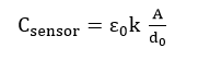
In order to calibrate the sensor, we have to understand how capacitance of the sensor is calculated. Capacitance of the sensor (Csensor) can be calculated from electrode area (A), dielectric thickness (d), and constants for dielectric permittivity of vacuum (ɛ0) and permittivity of the dielectric (k). In this model, when the sensor is stretched, the dielectric thickness and area of the electrode will change, resulting in a change in capacitance.
The baseline capacitance of the sensor is affected by the unstretched electrode area (A) as well as the permittivity of the dielectric (k) and the initial dielectric thickness (d0). The electrode area and dielectric thickness will depend on the application and size of sensor you choose, but the dielectric constant of the material will be a known value. The sensor shown here uses Ecoflex 0030 which has a dielectric constant of 2.8, as shown in the table below.
| Material | Dielectric Constant |
|---|---|
| Air | 1 |
| Ecoflex 0030 | 2.8 |
| Rubber |
7 |
| Water | 80 |
| Titanium dioxide | 80 |
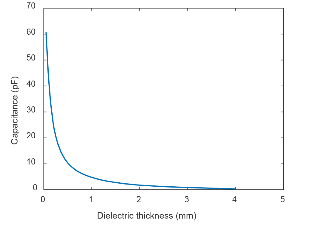
If another elastomer is chosen as the dielectric (as mentioned in our Design section), its dielectric constant will have to be looked up as it will increase or decrease the baseline capacitance. Using this model, the capacitance will decrease as the dielectric thickness increases, as shown in the figure below.
|
| Figure 1. Capacitance change as a function of dielectric thickness |
Advanced Model
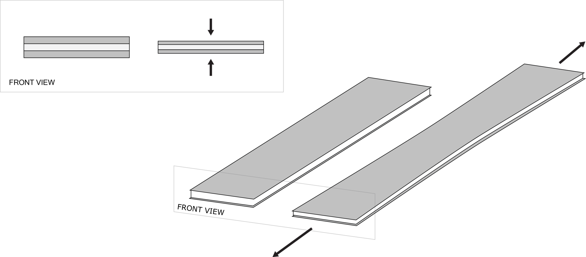
The initial equation for capacitance of the sensor can be expanded to take into account both area and dielectric thickness changes under applied strain as shown in Equation (2):
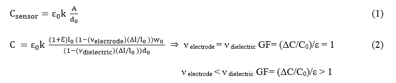
When the sensor is stretched to a given strain ε, the length of capacitor increases to (1+ ε) l0 while the width and thickness of the dielectric layer decrease to (1 – (νelectrode)(Δl/l0 ))w0 and (1 – (νdielectric)(Δl/l0))d0; where; l0, w0 and d0 are the initial length and width of the sensor and initial thickness of dielectric layer respectively and νelectrode and νdielectric are the Poisson’s ratios for the stretchable electrodes and dielectric layer respectively. If νelectrode is equal to νdielectric then the theoretical maximum gauge factor (GF) would be 1, but experimental results (Figure 2) on the Textile Silicone Hybrid Sensor lead to a GF above unity (max finding of 1.23). This is due to silicone penetration into the fabric layers filling air gaps and causing the sensor to resist perpendicular shrinkage from the applied strain which results in an overall increase in electrode area.
You will have to determine the guage factor for your sensor through experimentation. Read our Testing section for more details on how to set up experiments to test your sensor.

|
| Figure 2. Relative capacitance change as a function of applied strain for 20 cycles. A linear fit to part of the cycles with increasing strain is presented with a red dotted line, yielding a gauge factor of 1.23. |
Testing
To understand sensor performance, the electrical properties of a number of sample sensors were explored in dynamic and static tensile load conditions (A. Atalay et al. 2017). Tensile force was applied in the course direction of the knit structure for characterization of the hybrid sensor and the fabric electrodes.

|
Sensors were dynamically tested on a commercial electromechanical tester (Instron 5544A) . Capacitance was measured with a capacitance meter (Model 3000, GLK Instruments) connected to the integrated sensor leads with probes. Via a common I/O interface, (BNC-2111, National Instruments Corp. USA), the load, extension, and capacitance data were synchronously obtained and logged. All sensors characterized were produced in a standardized size (cut to 80 mm x 10 mm with integrated connectors) and have an active, stretchable area of 65 mm x 10 mm, due to the attachment of handles. Sensors were preconditioned by stretching to 100% applied strain for at minimum 10 cycles.

|
Verification
Changes in dielecric thickness and electrode area play an important role in capacitance change as the sensor is strained. Figure 1 shows area change measurements of a rectangle of just conductive fabric, a rectangle of just silicone and the textile silicone hybrid sensor corresponding to applied strain. Figure 1b. shows a higher area increase for the hybrid sensor under applied strain due to the penetration of silicone through the mesh structure of the fabric, which fills the inherent air gaps within the fabric structure and resists perpendicular shrinkage.
Figure 1c. shows a 16% plastic deformation for the fabric only sample under repeated cycles of 120% strain. Introducing silicone into the fabric network reduced the plastic deformation to 7% under identical conditions. The silicone also prevents rolling of the fabric from its edges after the stretching and relaxation cycles creating a more dimensionally stable structure.
| Figure a. | Figure b. | |

|

|
|
| Figure c. | Figure d. | |

|

|
|
| Figure 1. a) Representative sketch of area change for the sensor, the conductive fabric and the silicone. b) Area change as a function of strain from sensor, conductive fabric, and silicone. A second degree polynomial fit is applied to the data. c) Representative sketch of recovery after 150% strain for the sensor, the conductive fabric and the silicone. d) Plastic deformation percent for the sensor, conductive fabric, and silicone. A logarithmic fit is applied to the data. | ||
Testing Data
The influence of dynamic strain on the electrical performance of the sensor was investigated by stretching and releasing the sensor at 100% strain and a speed of 24 mm/s (Figure 1). The relative change in capacitance as a function of strain is highly linear based on a simple linear fit (R2 = 0.999) and corresponding gauge factor is 1.23 (Figure 2).

|

|
| Figure 1. | Figure 2. |
| Figure 1. Relative change in sensor capacitance upon triangular cyclic straining to 100% at 0.11Hz. Figure 2. Relative capacitance change as a function of applied strain for 20 cycles. A linear fit to part of the cycles with increasing strain is presented with a red dotted line, yielding a gauge factor of 1.23 | |
Drifting characteristics of the sensor under static loading was also measured. Drift error was calculated as the change in the sensor capacitance response to a constant strain value. The drift values of the strain sensor found were 0.3%, 0.7%, 0.6%, and 0.5% for the strain levels of ε = 0.25, 0.50, 0.75, 1.0 respectively.
|
|
| Figure 3. |
| Static drift of the sensor under constant strain levels at ɛ=0.25, 0.5, 0.75, 1.0 holding for 20 seconds. |

Other sensor performance experiments and results are listed in the table below. These experiments includes fatique performance at 1000 cycle to see long term usage performance of the sensor, sensor bandwith to see the covarage of human body activities which can reach upto 10 Hz. In addition, response time, hysteresis, resolution, and electromechanical failure characteristics also were investigated.
|
Applied test for characterization |
Sensor results |
|
Fatigue performance at 1000 cycle dynamic strain |
5% and 12 % decrease on signal amplitude at 25% and 100% strain respectively |
|
The temporal response of the sensor |
<30ms (including any delays related to instrumentation) |
|
Sensor frequency bandwidth at 10% applied strain |
Decrease on signal amplitude starting from 27Hz |
|
Max. Hysteresis |
0%, 0.2%, 0.7%, 1.5%, 2.5% for the applied strains at 25%, 50%, 75%, 100% and 125% respectively |
|
Resolution |
0.54% and 1.24% at 25% and 100% strain respectively |
|
Linearity |
R2 = 0.999 |
|
Gauge Factor |
1.23 |
|
Drift of the stain sensor under static loading for 20s |
0.3%, 0.5% drift for 25% and 100% respectively |
|
Electromechanical failure of the sensor |
Signal loss at 170%, permanent deformation on sensor elasticity and handle joints at 220% |
|
|
Case Study
To demonstrate the potential for the textile-silicone hybrid sensors to be used in human motion tracking applications, they were integrated into a glove for hand motion tracking (A. Atalay et al. 2017). With a limited surface area on the fingers the lower profile of the senor allowed for easy integration with the small surface area of the glove fingers. The sensors were mounted to the glove using Ecoflex 00-30 as an adhesive and micro coaxial cables were attached to the finger-sized sensors and connected to the non-stretch areas of the glove for a more robust connection.

|
These non-stretch areas were not part of strain measured and constructed only to provide anchoring points for the sensors to be attached to. Sensors placed across these joints were recording strain levels while the hand performed various movements.

|
The figure below depicts signal change recorded during flexion. The capacitance change for each finger was plotted after being recorded in real-time and utilized SSM-02-13 StretchSense sensor modules with Bluetooth capabilities.

|

|