Basic Model
In order to calibrate the sensor, we have to understand how capacitance of the sensor is calculated. Capacitance of the sensor (Csensor) can be calculated from electrode area (A), dielectric thickness (d), and constants for dielectric permittivity of vacuum (ɛ0) and permittivity of the dielectric (k). In this model, when the sensor is stretched, the dielectric thickness and area of the electrode will change, resulting in a change in capacitance.

The baseline capacitance of the sensor is affected by the unstretched electrode area (A) as well as the permittivity of the dielectric (k) and the initial dielectric thickness (d0). The electrode area and dielectric thickness will depend on the application and size of sensor you choose, but the dielectric constant of the material will be a known value. The sensor shown here uses Ecoflex 0030 which has a dielectric constant of 2.8, as shown in the table below.
| Material | Dielectric Constant |
|---|---|
| Air | 1 |
| Ecoflex 0030 | 2.8 |
| Rubber |
7 |
| Water | 80 |
| Titanium dioxide | 80 |
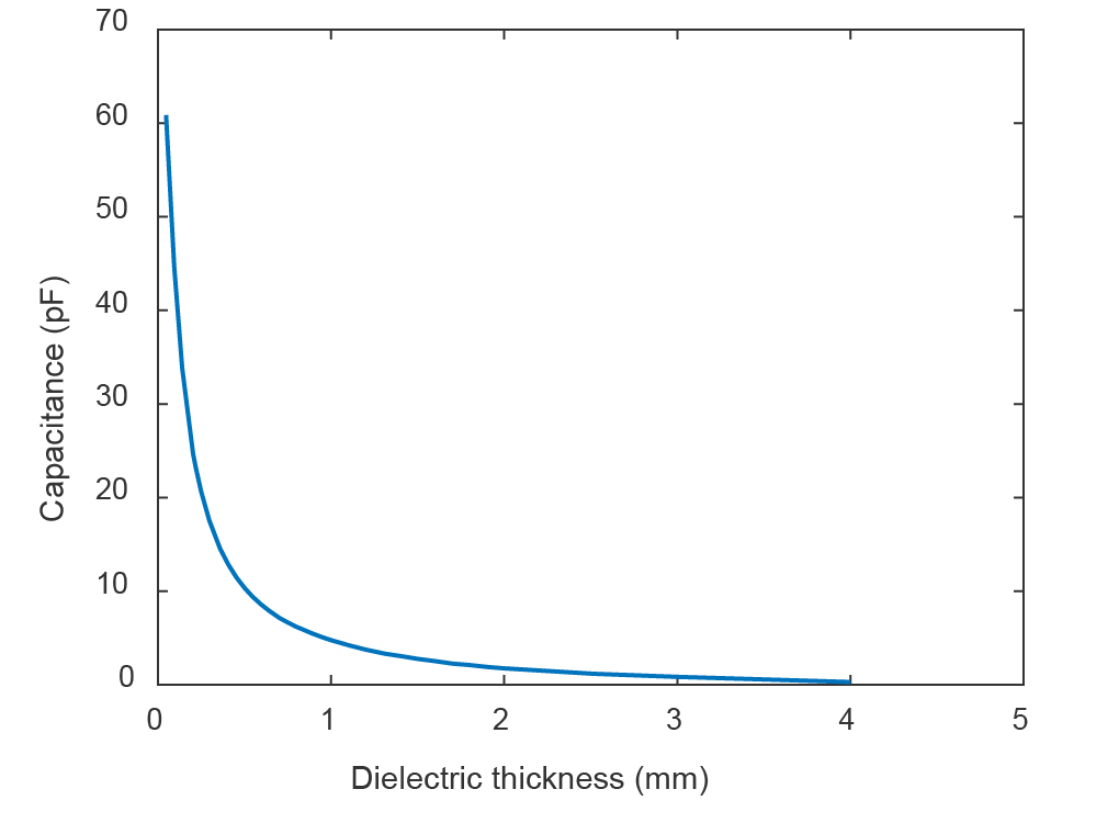
If another elastomer is chosen as the dielectric (as mentioned in our Design section), its dielectric constant will have to be looked up as it will increase or decrease the baseline capacitance. Using this model, the capacitance will decrease as the dielectric thickness increases, as shown in the figure below.

|
| Figure 1. Capacitance change as a function of dielectric thickness |
Advanced Model
The initial equation for capacitance of the sensor can be expanded to take into account both area and dielectric thickness changes under applied strain as shown in Equation (2):

When the sensor is stretched to a given strain ε, the length of capacitor increases to (1+ ε) l0 while the width and thickness of the dielectric layer decrease to (1 – (νelectrode)(Δl/l0 ))w0 and (1 – (νdielectric)(Δl/l0))d0; where; l0, w0 and d0 are the initial length and width of the sensor and initial thickness of dielectric layer respectively and νelectrode and νdielectric are the Poisson’s ratios for the stretchable electrodes and dielectric layer respectively. If νelectrode is equal to νdielectric then the theoretical maximum gauge factor (GF) would be 1, but experimental results (Figure 2) on the Textile Silicone Hybrid Sensor lead to a GF above unity (max finding of 1.23). This is due to silicone penetration into the fabric layers filling air gaps and causing the sensor to resist perpendicular shrinkage from the applied strain which results in an overall increase in electrode area.
You will have to determine the guage factor for your sensor through experimentation. Read our Testing section for more details on how to set up experiments to test your sensor.

|
| Figure 2. Relative capacitance change as a function of applied strain for 20 cycles. A linear fit to part of the cycles with increasing strain is presented with a red dotted line, yielding a gauge factor of 1.23. |
