Subsystem Testing
Object Manipulation System
Arm testing
Once a few layers of the arm were created they were testing using a lab air supply to measure the inflation time, deflation time, and how much each layer would expand. An external air compressor was used to inflate each channel individually by manually opening the flow paths to each arm channel. The final number of layer was then determined based of the expansion size to allow for the desired reach. The necessary air pressure to operate the arms was also determined. In testing, it was discovered that the lower layers would expand to their maximum capacity before the upper layers would fully inflate. To compensate for this, the silicone thinner was only used in the upper layers since it reduced to strength of the material. Doing so allowed for a more uniform inflation of the arm. Directional control was also tested to ensure this method would work as intended.


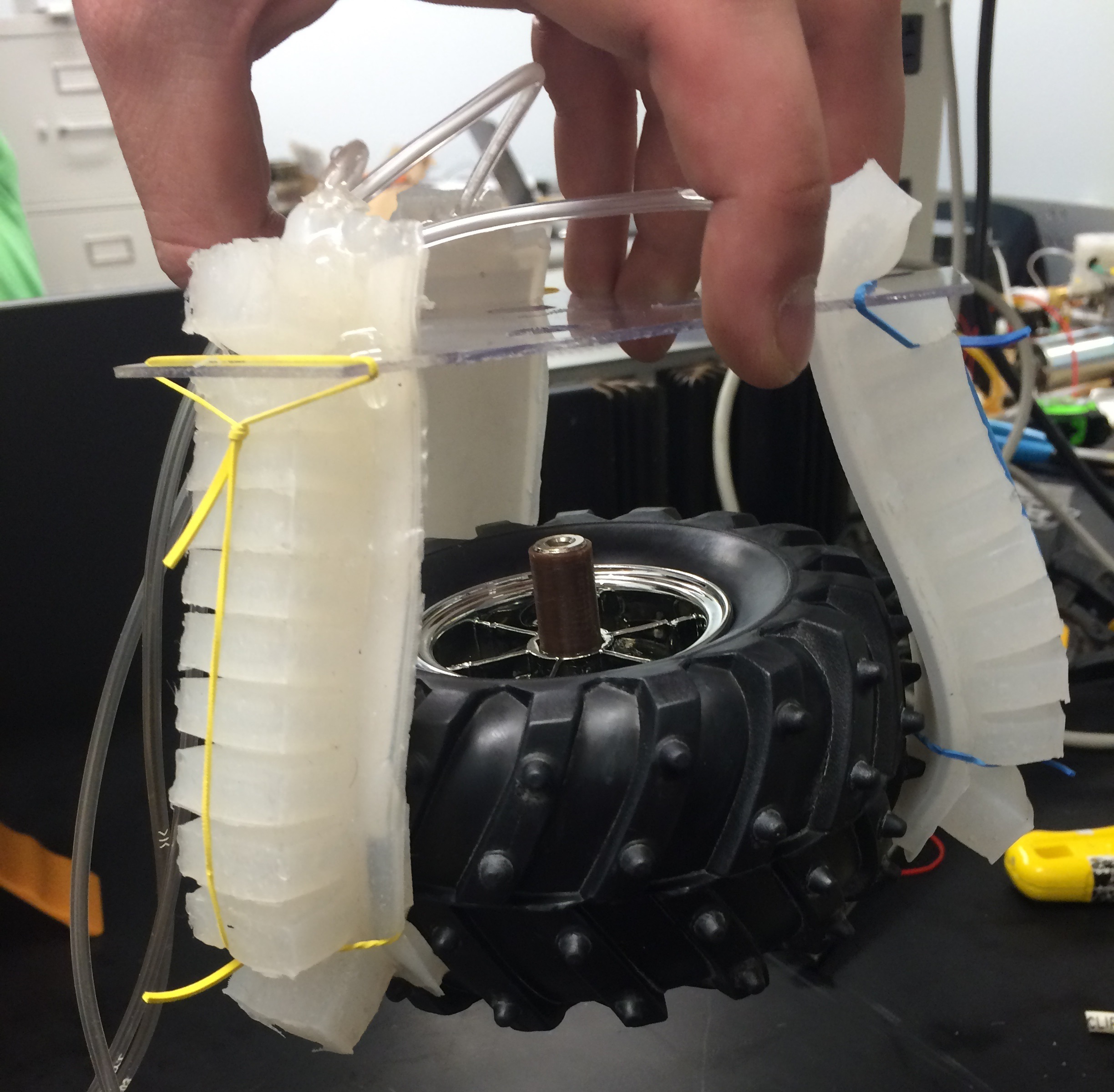
Finger Testing
Testing using the external air compressor was also performed on the finger to determine inflation time, deflation time, and maximum pressure. It was also used to determine the strength of the fingers when inflated. Once of the tires was used as a test object to ensure the fingers were strong enough to grasp a tennis ball.


Air Flow System
Once built, the air flow system was tested using an external air compressor. First testing was done to find any leaks. Soapy water was applied to all connection to determine if air was leaking from the connection. Any holes found were sealed closed. Each solenoid valve was tested using a DC power supply to open and close them when under pressure. The compressor was also tested to determine how long it would take to inflate the tank. The compressor was able to pressurize the air tank to 100 psi in under 30 seconds. Each part of the system was also tested at incrementally higher pressure to determine all connection were stable, even when pressurized beyond what the expected pressure would be. The entire system was tested up to 100 psi. The pressure transducers put out an analog voltage based on the pressure. A correlation between applied pressure and output voltage was created to later be used in the controls.
Control System
The controls for the system was tested as the subsystem were combined. Initial testing was performed to ensure the output voltages from the Arduino were functioning properly when connected to the gaming controller. Once the power system was complete, the outputs from the power system were checked to ensure they were functioning properly. Once combined with the flow loop and navigation systems, the functions were continuously tested to work out any bugs.
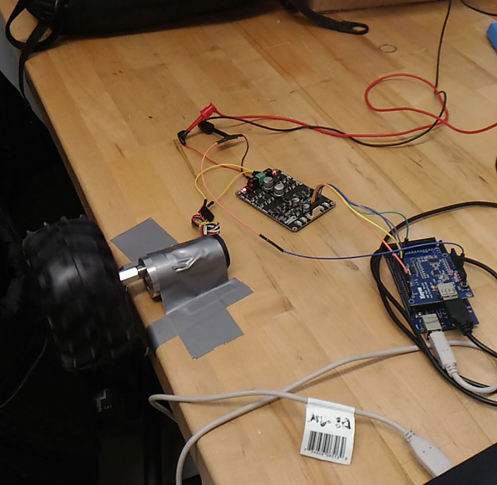
Navigation System
To test the navigation system, the motors were first hooked up to the driver board and the Arduino. Directional and speed control were tested to ensure proper functionality. Most testing on the navigation system occurred later once it was integrated into the rest of the system.
Power System
The circuit was first testing using Texas Instruments Webench design center. Once built the circuit was tested using a DC power supply and a multimeter to test the performance. Once integrated with the control, the MOSFET testing was also performed to ensure the functioned as required.