1. Force transfer by constrained string (Main) - Fabrication
This section describes the fabrication of the "on-eyelid" parts and their connection to the glasses/actuator set-up.
Materials & Equipment:
Item | Description | Key Facts/Values | Identification |
4 x AA Battery Holder | Power source holding 4 AA batteries, output of ~6V |
| |
Glasses | Standard Laboratory Safety Glasses | N/A | N/A. |
Eco-flex Silicone 00-30 | Low durometer, castable silicone elastomer, |
Certified as per ISO 10993-10, Biological evaluation of medical devices, Part 10: Tests for irritation and skin sensitization | |
Firgelli LAC (Control Board) | Soldered to power supply, allows for computer based actuator position control. | N/A | |
Kevlar Thread | For attachment of actuator to eyelid | .014" | |
BandAid Clear Waterproof Adhesives | For attachment of silicone parts to eyelid/skin | N/A | N/A |
Sil-poxy (Epoxy) | For connecting parts (e.g. actuator to glasses, or fibre starting point to silicone part no (1). | N/A | |
Firgelli Linear Actuator (PQ-12) | For actuation to provide linear force and motion. | Outlined in more detail in following paragraph. | |
Polyurethane Tubing | For connecting glass and lid components. | 1/16" ID, 1/8" OD, | |
Luer lock | For connecting glass and lid components. |
|
|
Table 3‑1: Materials used in fabrication of linear device.
The actuator had a maximal displacement of 20mm, with built in position feedback potentiometer to allow for position control. It is capable of achieving a maximal force of 18N. The actuator was powered by a ~6V power supply. It has a speed of 28mm/s.
Fabrication Methods:
1) Test devices fabrication:
Test devices, consisting of three components of (1) the nasal attachment, (2) the "on eyelid" part and (3) the lateral directional constraint, were made by casting of silicone in 3D printed moulds.
a) An approximately 1:1 ratio by volume of the A & B mixtures of the silicone elastomer (Eco-Flex 00-30) were mixed in a plastic bowl.

b) After thorough mixing, the mixture was poured into the moulds. (The moulds were designed in Solidworks and 3D printed, STL files are available in the design section).
c) Struts were pushed into the silicone such that they would become embedded into the final cured structure.
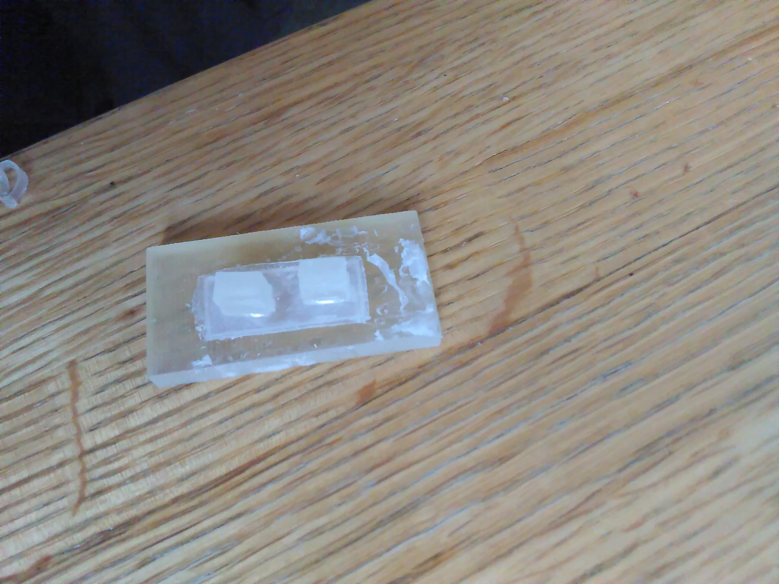
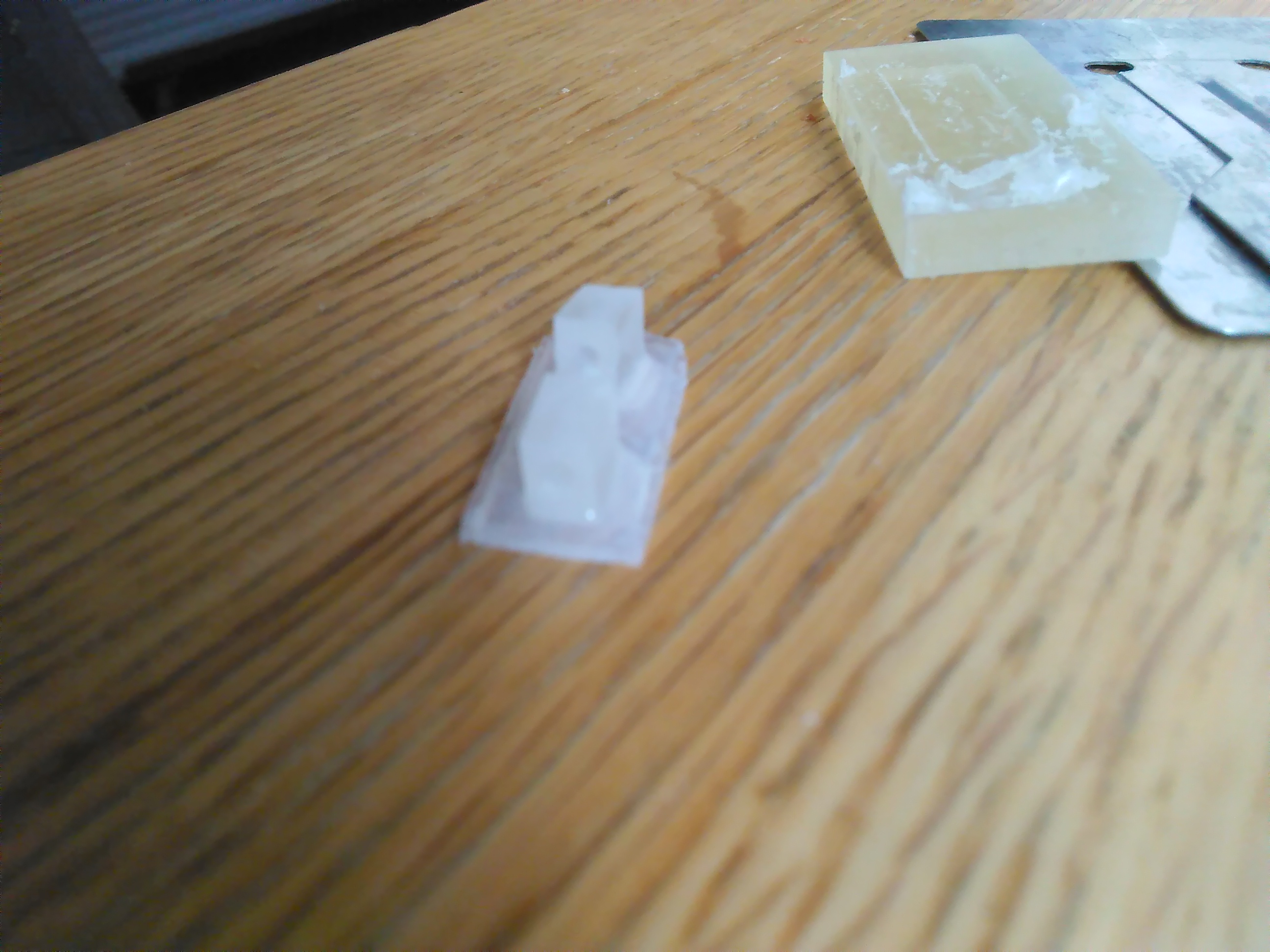
d) The parts in the moulds were cured in an oven at 60 degrees for 15 minutes. Parts were removed from moulds after cooling using a straight razor. Some parts in moulds and removed parts are shown below.

2) Connection of individual "on-face" parts
a) After curing, Kevlar thread was inserted into the holes present in the struts, connecting the three mould pieces in the correct order, from 1-3
b) The thread was intended to originate from part number (1), and as such, was fixed in position by affixing the thread to the mould part using epoxy glue which was allowed to cure and solidify for 15 minutes.

(Note: The above image has an orange-brown liquid latex sample on the left which was used to test whether encapsulation in cured epoxy would be a suitable fixation mechanism, this wasn't used in testing.)
c) At this point, the thread orginated from its position in part (1), the nasal end (fixed by epoxy), travelled through (2), the "on-eyelid" piece and then (3), the lateral direction constraint. It was then fixed at this point to a strip of polyurethane tubing that could connect to a Luer lock from the actuator/glasses end. This done by inserting the thread into the tubing and applying epoxy and allowing to cure. The connection (as a bench set-up) is shown below.

(Note: Here peripheral items such as band-aids are shown below/around the parts. This is because at this point the aim was to use epoxy to glue adhesive to the silicone, this was abandoned later. Additionally, a bottom eyelid piece is connected here in parallel to the top eyelid piece, this was not used.)
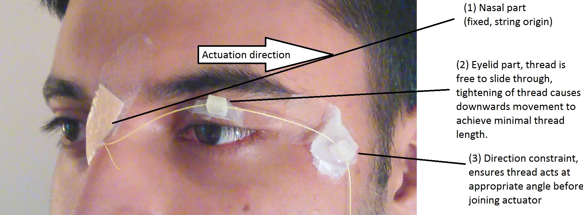
d) The set-up was attached to the face/eyelid, using band-aid as adhesive. The following image describes the set-up.
3) Actuator component
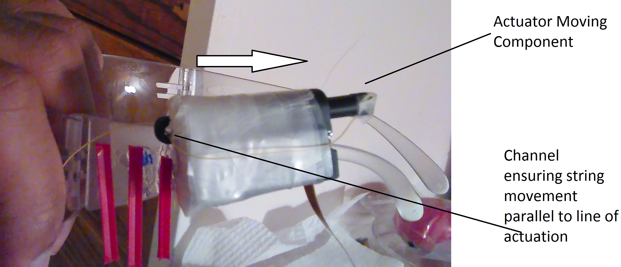
a) A Firgelli linear actuator was wrapped in parafilm and then attached using epoxy to the left hand side of a pair of glasses. It was oriented so the actuating component was facing (and actuating) in the posterior direction. String was attached to the moving actuator component and then passed through a small protruded channel on the anterior end of the actuator that colinear with the line of action of the actuator. This ensured that no matter the angle between the direction constraint part and the actuator, actuation relative to the moving part would always occur in its line of actuation, maximising distance. This is illustrated below.
b) The actuator (Firgelli PQ-12) was connected to its control board (Firgelli LAC), which was connected to power (4xAA batteries) and a PC via USB connection. Due to the short length of the control board-actuator connection, the control board had to be held in the hand during testing.
c) The actuator thread was connected to the on eyelid section by connecting the Luer lock at the end of the actuator thread to the polyurethane tubing described earlier.

As the string is obviously far too loose in the pictured image, the thread on the eyelid end was cut and shortened until in a resting state, a small amount of displacement applied to the string was sufficient to apply tension to the eyelid. The total length of the thread (actuator and eyelid end) at this point was ~11cm.
(Note: During final live testing, the thread from the luer lock was pulled out of its connecting epoxy, so string was directly tied to the actuator component, bypassing the luer lock/tubing connection.)