2. Lateral Pulling Fabrication (Preliminary Design)
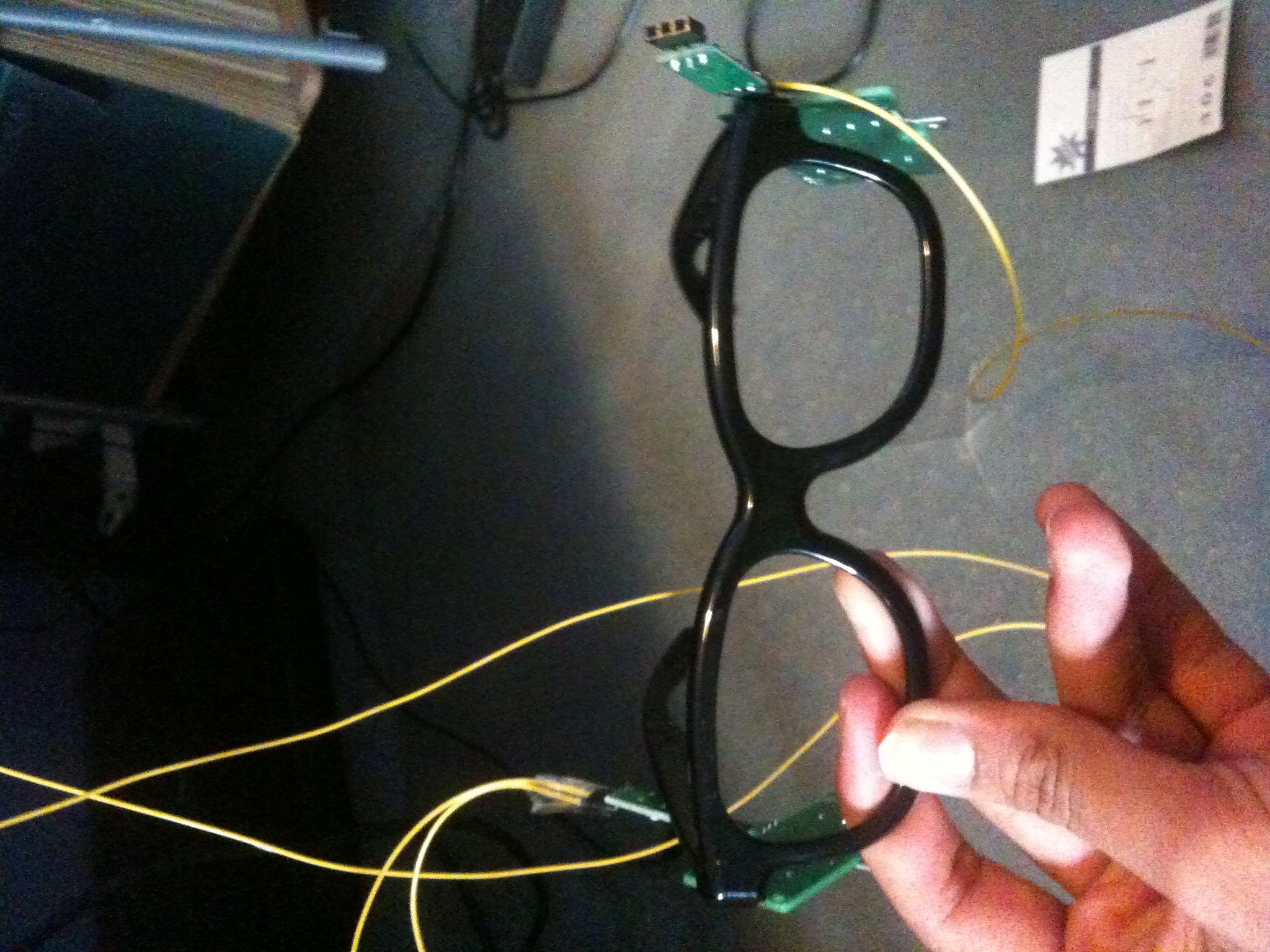
A sling device was fabricated by attaching a shape memory alloy actuator to the side of a pair of 3D glasses. The actuator was situated on the side of the glasses corresponding to the eyelid being closed. The actuator was not fixed permanently to the glasses; rather it was affixed using blu-tack to allow for adjustment of distances and lines of action, as outlined in the testing section.
Properties of materials and equipment used, as well as any methods for fabricating components or set ups are described below.
Materials & Equipment:
Item | Description | Key Facts/Values | Identification |
Benchtop power supply | Power outputs of 10V and 5V and two ground outputs. | 10V was used for this experiment. | LABEQ-335, from GSBME Teaching Laboratory |
Glasses | 3D glasses with the lenses removed | N/A | N/A. Obtained from Event Cinemas. |
Connective Electrical Equipment | Standard electrical wiring and lead free solder | Copper Wire diameter (.6mm)
| Obtained from Jaycar electronics |
Miga Motors MAD Microcontroller | Soldered to actuator and power supply, allows for push button actuator operation | N/A | MAD-3561 |
Household string | For attachment of actuator to eyelid | N/A | N/A |
BandAid Clear Waterproof Adhesives | For attachment of string to eyelid | N/A | N/A |
Blu-tack | N/A | N/A | N/A |
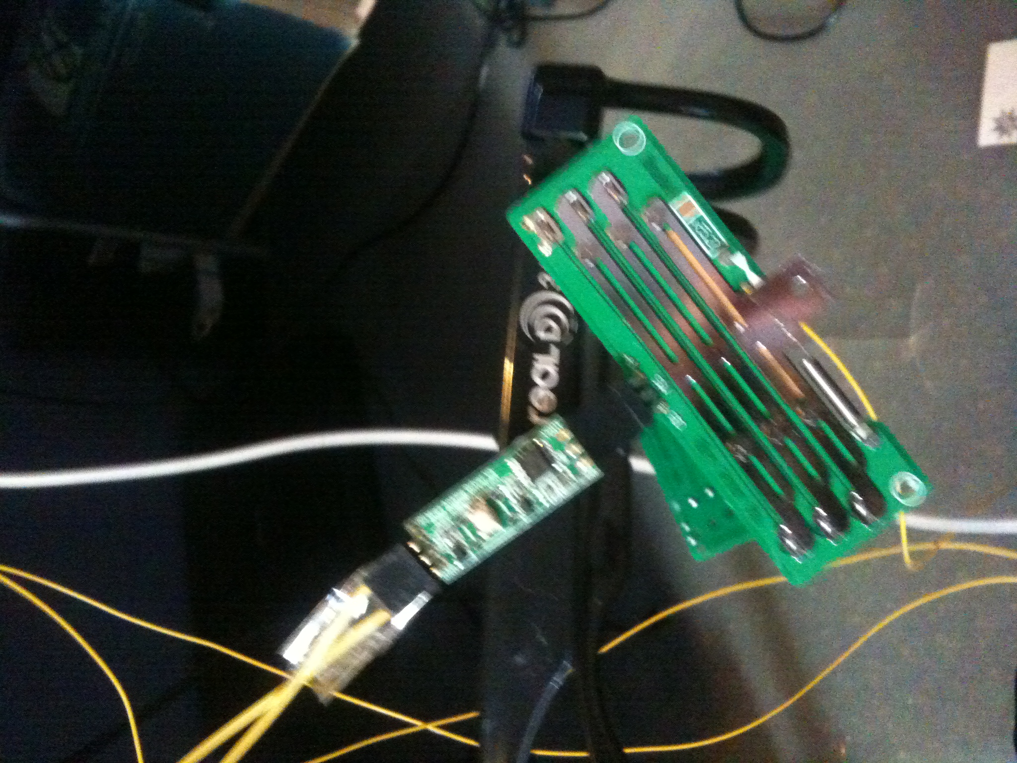
Miga Motors Shape Memory Alloy Actuator | For actuation to provide linear force and motion. | Outlined in more detail in following paragraph. | Miga One Linear Actuator |
Table 3‑1: Materials used in fabrication of linear device.
One actuator had a maximal displacement of 8mm and a maximal force of 8.9N. The other had a maximal displacement of 6mm and a maximum force of 7.2N. The actuator was powered by a 10V power supply, allowing it to reach peak displacement in 200ms.
Fabrication Methods:
Connections between electrically active components were made by soldering connecting wires onto appropriate areas or joining using alligator clips. Connections were made between power supply and the MAD controller & between the controller and the actuator.
Mechanical connections between components were made using blu tack or Bandaid adhesive. This was considered sufficient for the present tests. Connections were made between the actuator and string (Band-Aid), actuator and glasses (Blu-tack) and string to eyelid (Band-Aid).
A side view of the preliminary prototype is shown below:
A front view is also shown: