Integrated System Fabrication
Once all the subsystems were created, integrating them together was just a matter of making all the connection. The following process was used to do so.
Object Manipulation and Air Flow Loop
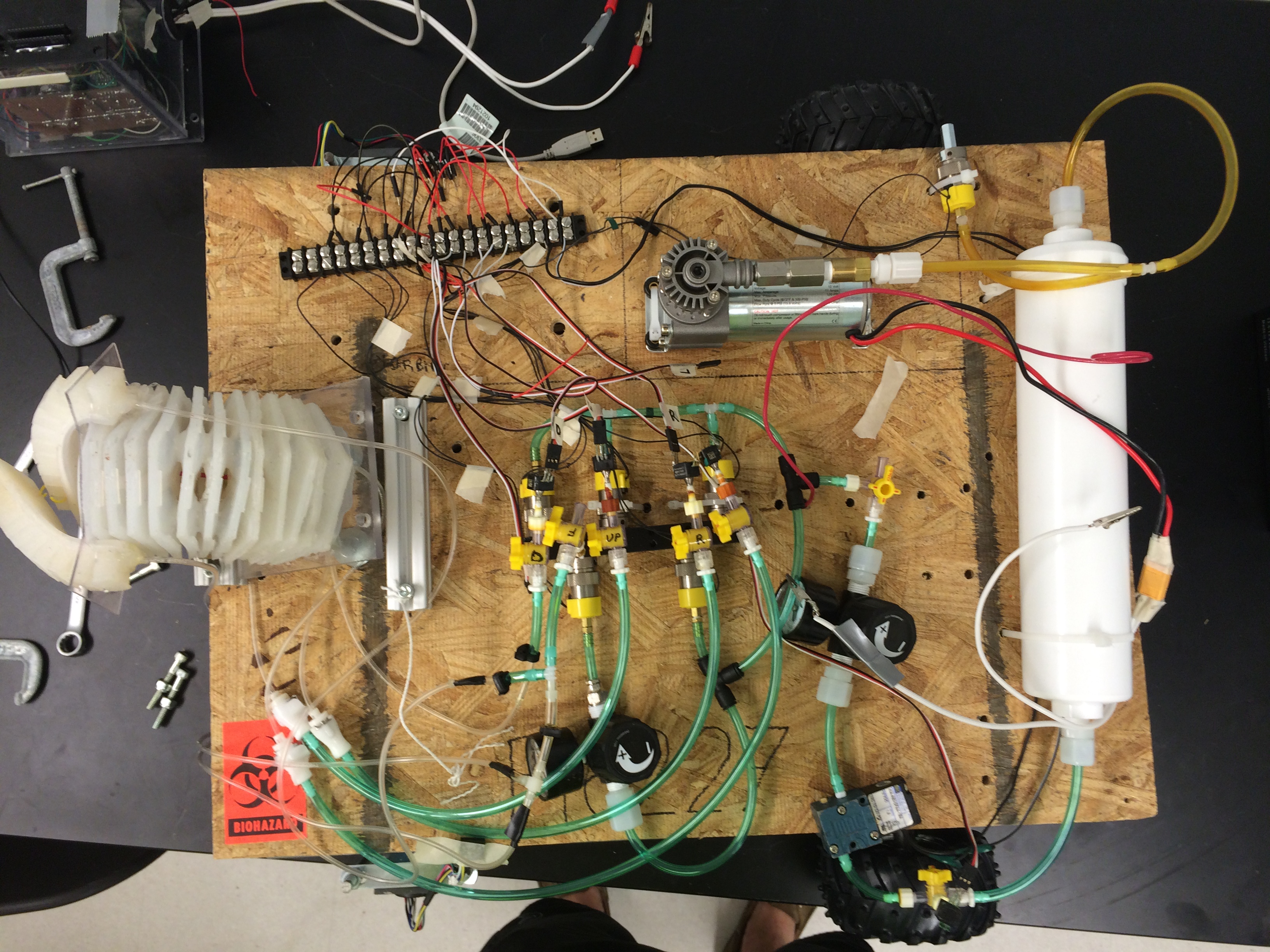
Simple T-Connectors with detachable fittings were used to split each outlet from the manifold to the pressure sensor and the arm or fingers. Barbed quick connectors were used to connect the 1/4" tubing leaving the manifold to the 1/16" tubing leaving the fingers and arms. The quick connectors allowed for easy removal of the arm in case any repairs were needed. The base of the arm was attach to a hinge and the hinge to a 1" x 1" piece of 80/20. The 80/20 was then attached to the plywood board. A square u-bolt was placed underneath the base of arm and secured using nuts. The height of this u-bolt could be adjusted so that the arm could sit flat or at an incline. The wires from each solenoid valve and the pressure sensors were all connected to a single rail to better organize the system. The wiring for the compressor and motors were kept separate as they would draw much more current than the valves and transducers and would require larger gauge wire.
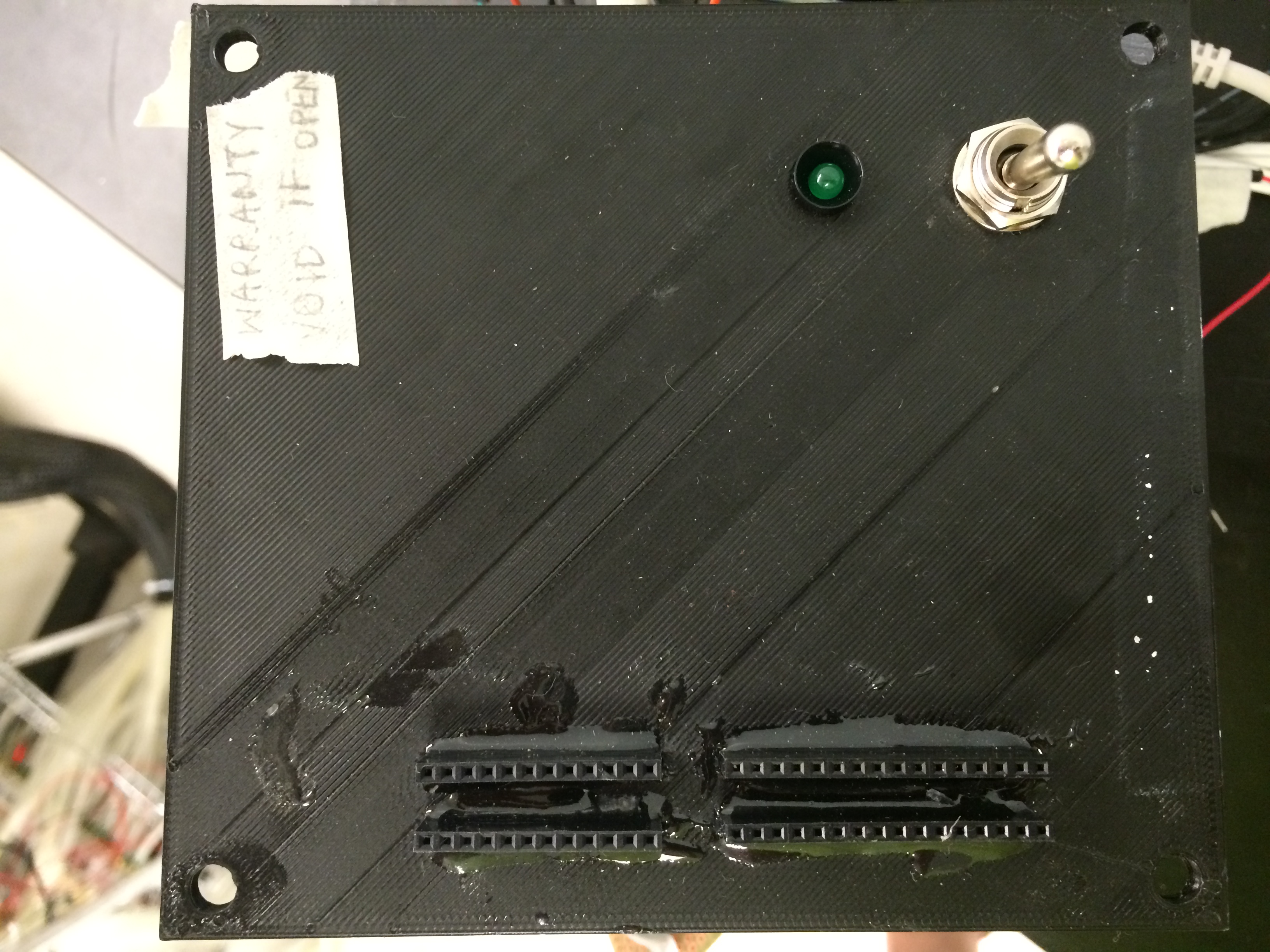
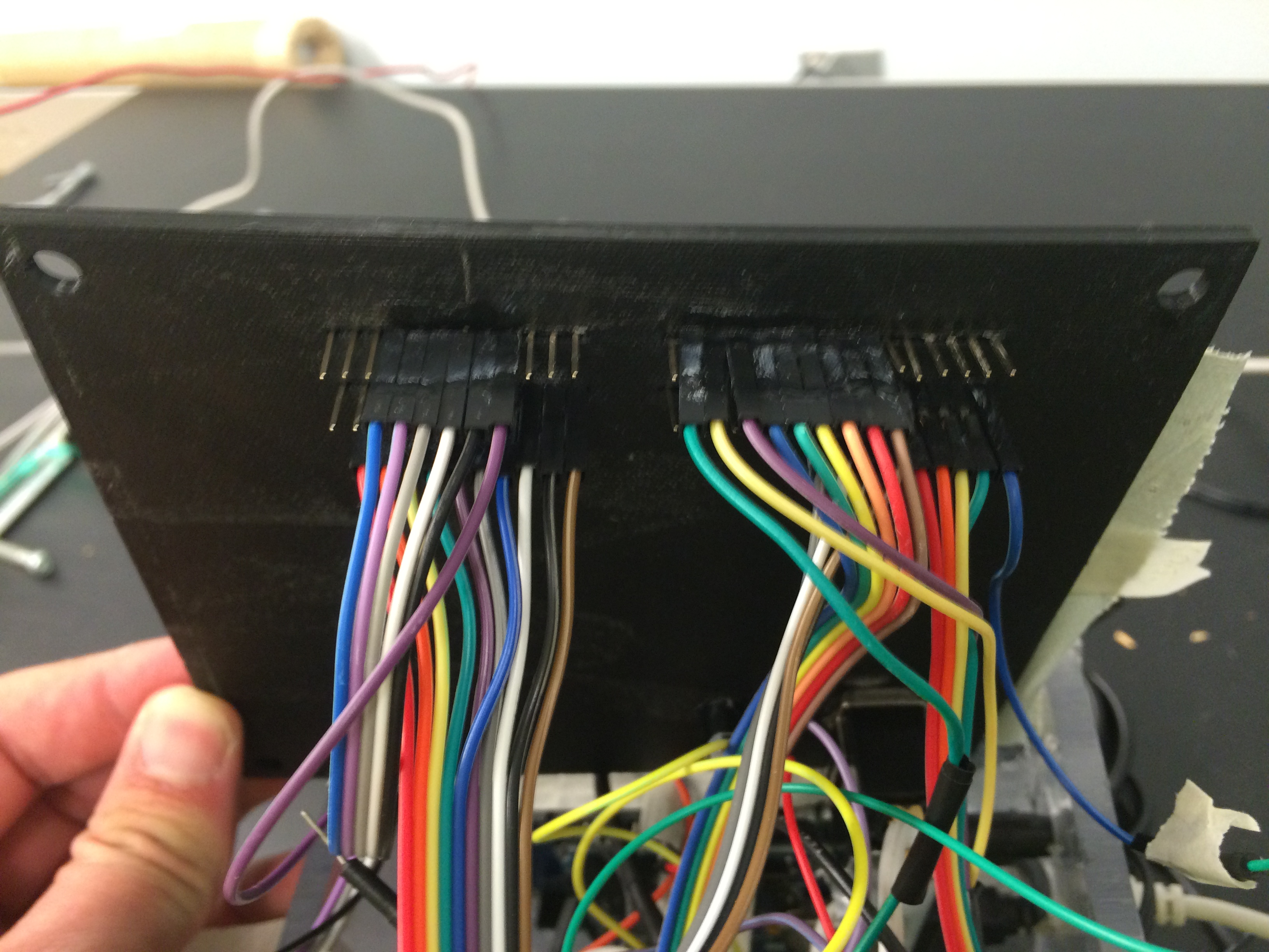
Electrical Consolidation
In order to protect the circuit boards, a box was made from acrylic to house them all. A lid was 3D printed to allow for a switch to turn the system on and off as well as to allow for headers to connect the solenoid valves and pressure transducers to their appropriate connection. The headers also had ground, 5V, 12V, and 24V outputs for accessories. Holes were made on the side of the box as shown below to allow for connections to the gaming receiver, the battery, the compressor and the motors. Again, since those components drew much larger currents they could not be run through the headers on the top. A hole was also made to attach the USB connector from the Arduino to a computer to make any updates necessary without having to remove the Arduino from the box.