Subsystem Fabrication
Object Manipulation System
The object manipulation system contained two primary components: the arm and the fingers. As such, the fabrication was divided into each of these.
Arm
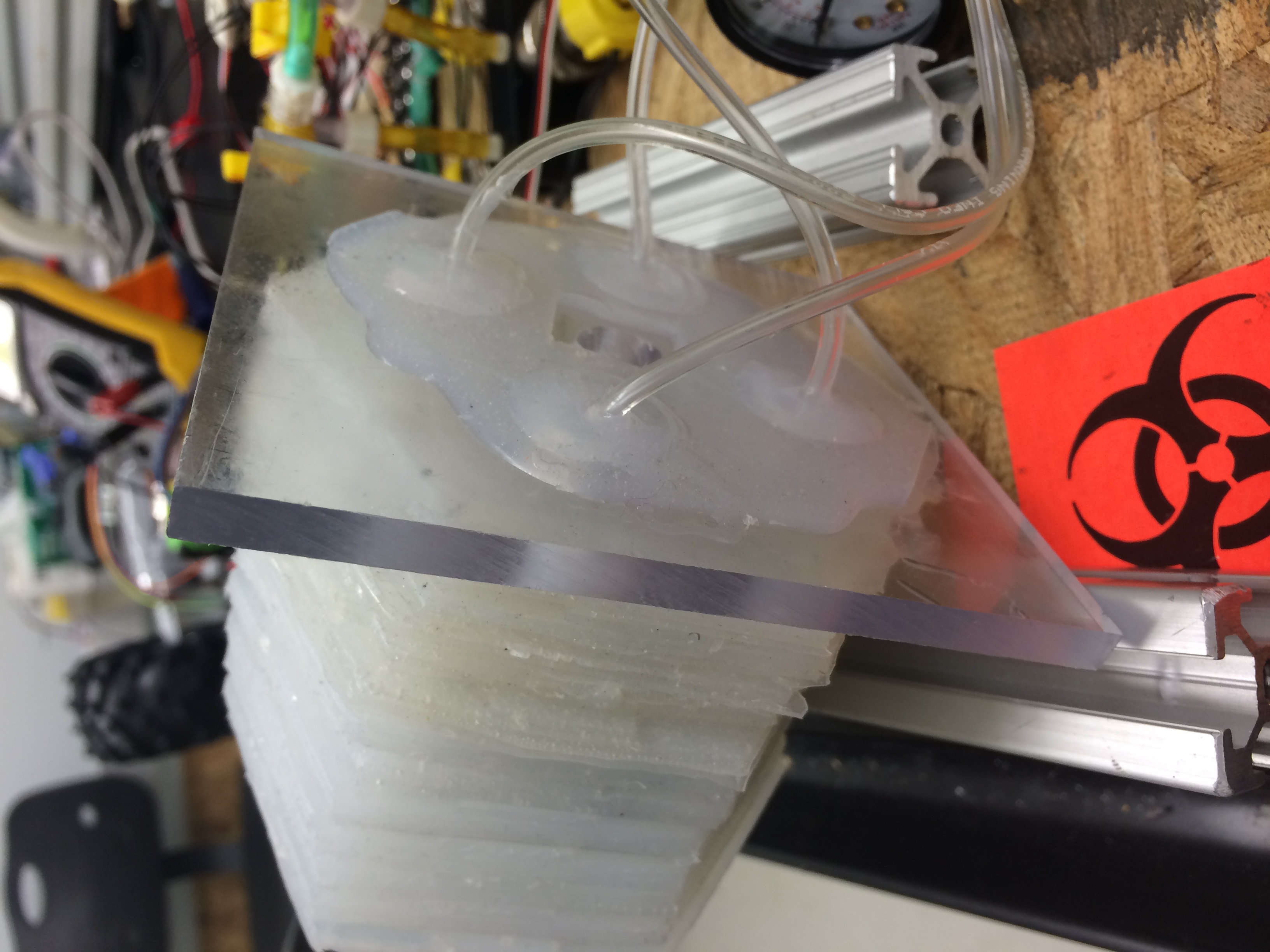
The arm consisted of a 4 channel design as shown in the subsystem design section. The process was very similar to another soft robot shown here. First a mold was created out of acrylic so that a liquid epoxy could be poured into it. The mold was made up of three layers of 6"x6"x1/16" acrylic glued together. The top layer had a hexagon with 2" sides cut out of the center. The middle layer had 4 1/2" diameter through holes where the layers would connect to one another and also had square holes cut out along the edges of the hexagon to act as standoffs. The bottom layer was solid. A fourth piece of acrylic was also cut with the same hexagonal shape in the center as the third layer, but not glued to the other three layers to simplify the building process. The mold can be seen here.


A two part epoxy was used to create the arm. Smooth-on Dragon Skin 10 was used with a Silicone Thinner. The thinner was only used to make the upper arm layers because the decrease the strength of the material and it was found that the lower layers needed to be stronger to withstand the strain caused by actuating the arm. The bottom five layer of the arm did not use the thinner. The upper layers used the thinner to help remove air bubbles which were common failure points in testing. The epoxy and thinner was mixed and then put into a vacuum chamber to remove all the air bubbles from the mixture. It was then poured slowly into the mold so no air bubbles were created. Plastic grocery bags were then cut into shape to create the four air pockets in the arm. Since the epoxy would not stick to the plastic bags, the pocket would inflate when pressurized with air. The shape can be seen in the image directly above. Approximately 6mm of space was left between the edges or center lines and the cavity edge. More epoxy was then mixed, the fourth layer of acrylic was placed over the mold, and the upper layer of epoxy was poured in. The epoxy cured in roughly 30 minutes. They layer could then be removed and holes were drilled through the layer where it would connect to the layers above and below it. A square hole was also cut in the center of each layer. This process was repeated to create 12 layers. To attach each layer to one another, a small amount of epoxy was place on the circular connecting pads and the layers were placed on top of one another. Once dry, four holes were drilled to create four continuous channels running the length of the arm. The bottom layer was attach to a 1/2" piece of plastic by drilling four holes in the plastic where the 1/2" diameter standoffs protruded from the bottom layer. More epoxy was used to secure the layer to the plastic base. Tubing was inserted into each of the four channels and glued with epoxy to later be connected to the flow system. This can be seen in the image below.
Fingers
The PneuNets Bending Actuator was used to create the fingers. The molds were 3D printed and the process that is outlined on the website was used to create three fingers. The same Dragon Skin 10 material was used to create the fingers. The mold used can be seen below. Plastic tubing was then inserted into one end of the finger and glued using epoxy to later be attached to the flow system.

A 1/16" piece of plastic was cut into a hexagonal shape with extra room left on three of the six sides to mount the fingers. An image of the mounted fingers can be seen below. The three air lines from the fingers were tied into one so all the fingers would actuate at the same time. Rubber bands were attached to the fingers and finger base to keep them from falling inward during use.

The base of the fingers was then attached to the top layer of the arm using the same epoxy. The final product can be seen below.

Air Flow System
The air flow system was built on a 18"x24"x1/2" piece of plywood. The following schematic was used as the design for the flow system. Each part was held down to the plywood using bolts or zip ties wrapped through holes drilled in the plywood.
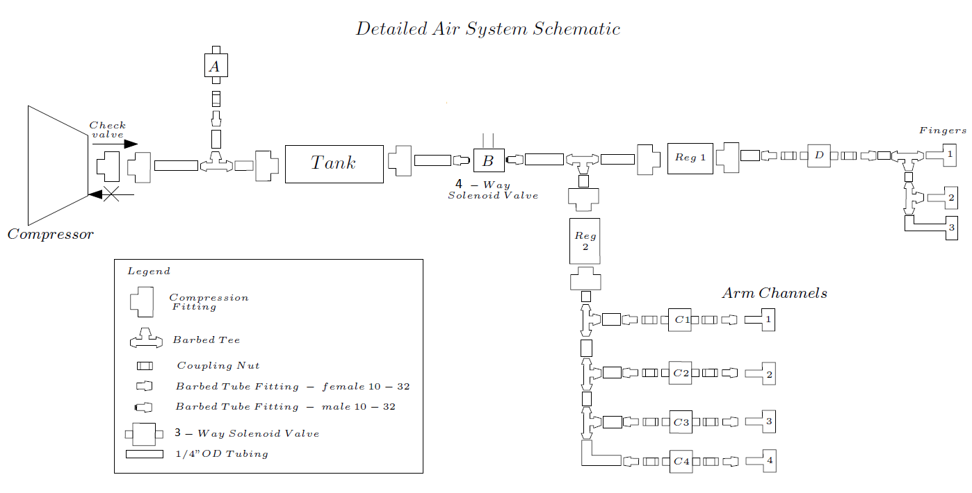
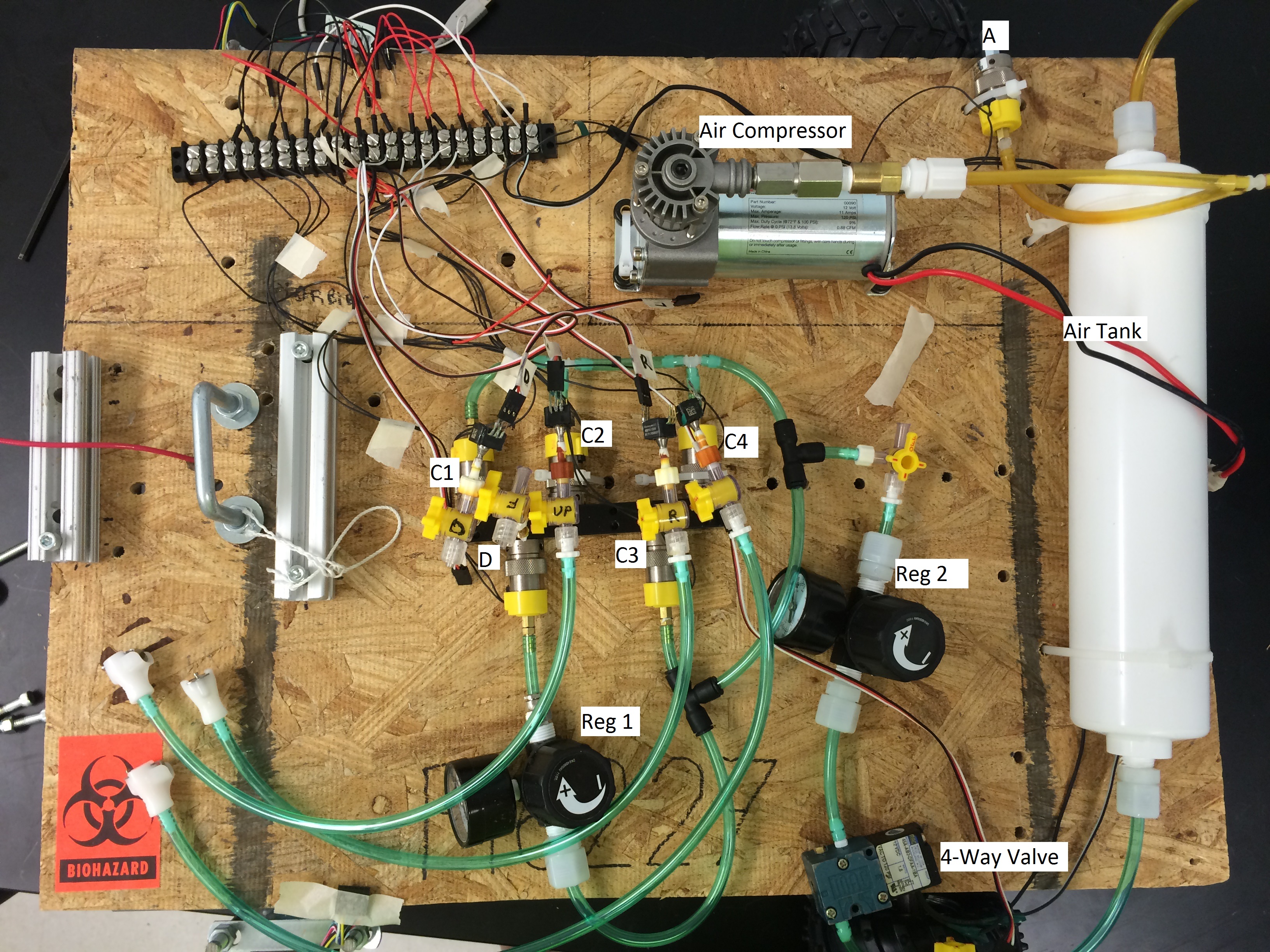
The final test loop was very similar to what is shown above with just a few small changes. For space saving reasons, the line split to the fingers was made after regulator 2 instead of before. Since the fingers were expected to operate at a much lower pressure than the fingers, this would not cause any issues. The other change was that solenoid valves C1-C4 and D were all tied into a manifold. This was down because the type of solenoid valves used here required a manifold to work properly. Those solenoid valves were also modified so no air could escape through the exhaust. If this modification had not been made, any compressed air in the arm or fingers would be released to the atmosphere when the valve was closed and the hand would not have been able to maintain a stationary position when pressurized. Teflon tape was used to seal any threaded connections to prevent air leaks. Compression fittings were also used when possible to prevent air leaks and ensure no connections would come loose at higher pressures. Additionally, a pressure feedback system was also added. Six pressure transducers were added into the system to relay pressure information to the control system. One transducer for each arm channel, one for the finers, and one for the tank were installed. The final flow loop can be seen below.
Control System
A USB Host shield is used to interface the Arduino Mega 2560 and the gaming receiver. A wireless Microsoft Xbox 360 remote controller is used to control the outputs from the arduino. The controls mapping is shown in the table below.
Button | Function |
Left Trigger (LT) | Drive Forward |
Right Trigger (RT) | Drive Backwards |
Left Joystick | Drive Steering |
D-Pad | Select Arm Direction |
A | Inflate Selected Channel |
B | Deflate Selected Channel |
Start | Inflate All Channels |
B + Start | Deflate All Channels |
Y | Inflate (Close) Fingers |
B + Y | Deflate (Open) Fingers |
Back | Activate Compressor |
Some automated control were also built into the controls as well. These incorporated the pressure feedback from the air flow loop. Their controls and function are shown in the table below.
Control | Limits | Action |
System Air Pressure Fail Safe | 100 psi | If pressure exceeds upper limit Release Valve A is opened to lower the system air pressure. |
Operating Pressure Control | 20 psi | If pressure drops below the limit during operation the compressor is turned on in order to maintain pressure at operating levels. |
Arm Pressure Control | Calibrated for each channel; nominally 2 psi | Each channel has variation in structure due to an imperfect fabrication system. This variation leads to each channel having a different movement response for any arbitrary pressure. To control this the pressure limits in each channel are calibrated in order to ensure full inflation leads to a completely vertical movement response. |
Arm Pressure Fail Safe | 2 psi | In case of a malfunction of a pressure sensor if any channel reaches 2 psi the valves will close for all channels. |
All software was developed in the Arduino IDE and written in Arduino C++.It runs a main loop which calls subsystem functions. The program is broken into subroutines that handle the different aspects of the robot. The code can be found here.
Navigation System
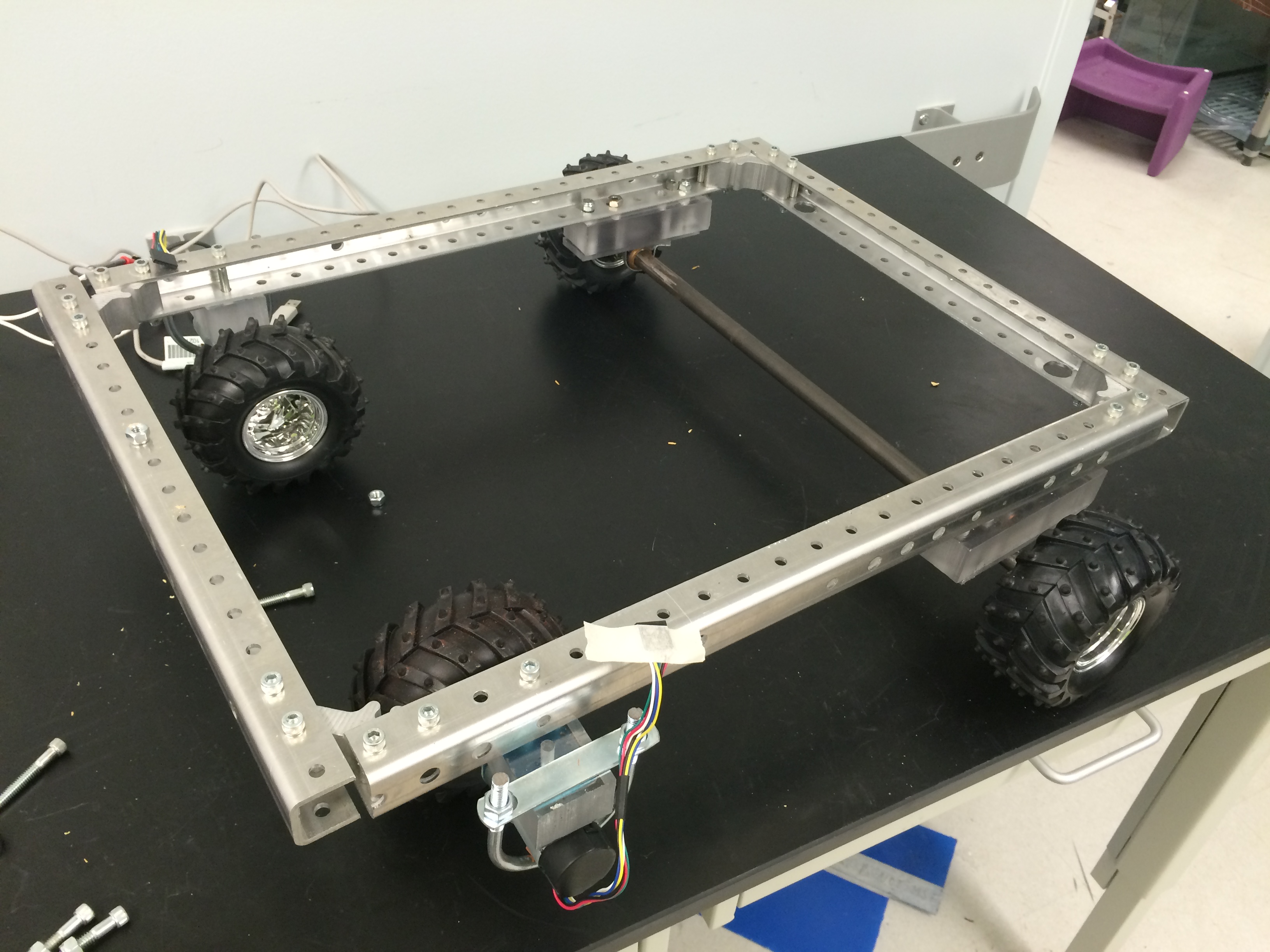
The navigation system consisted of a 18"x24" frame made of 80/20. The motors were mount on L-Brackets and then attached to plastic spacers which were attached to the frame using 1/4" bolts. The wheels were attached directly to the motors. The motorized wheels were placed at the front of the frame to make it front wheel drive. Since there was no built in turning capabilities, the hope was that a front wheel drive system might allow turning my spinning only a single wheel at a time. The back wheels were rigidly attached to an axle that was mounted to the frame using pillow blocks. Spacers were also used between the pillow blocks and frame to ensure the wheels had enough clearance and the frame would sit level with the ground. A picture of the complete frame can be seen below.
Power System
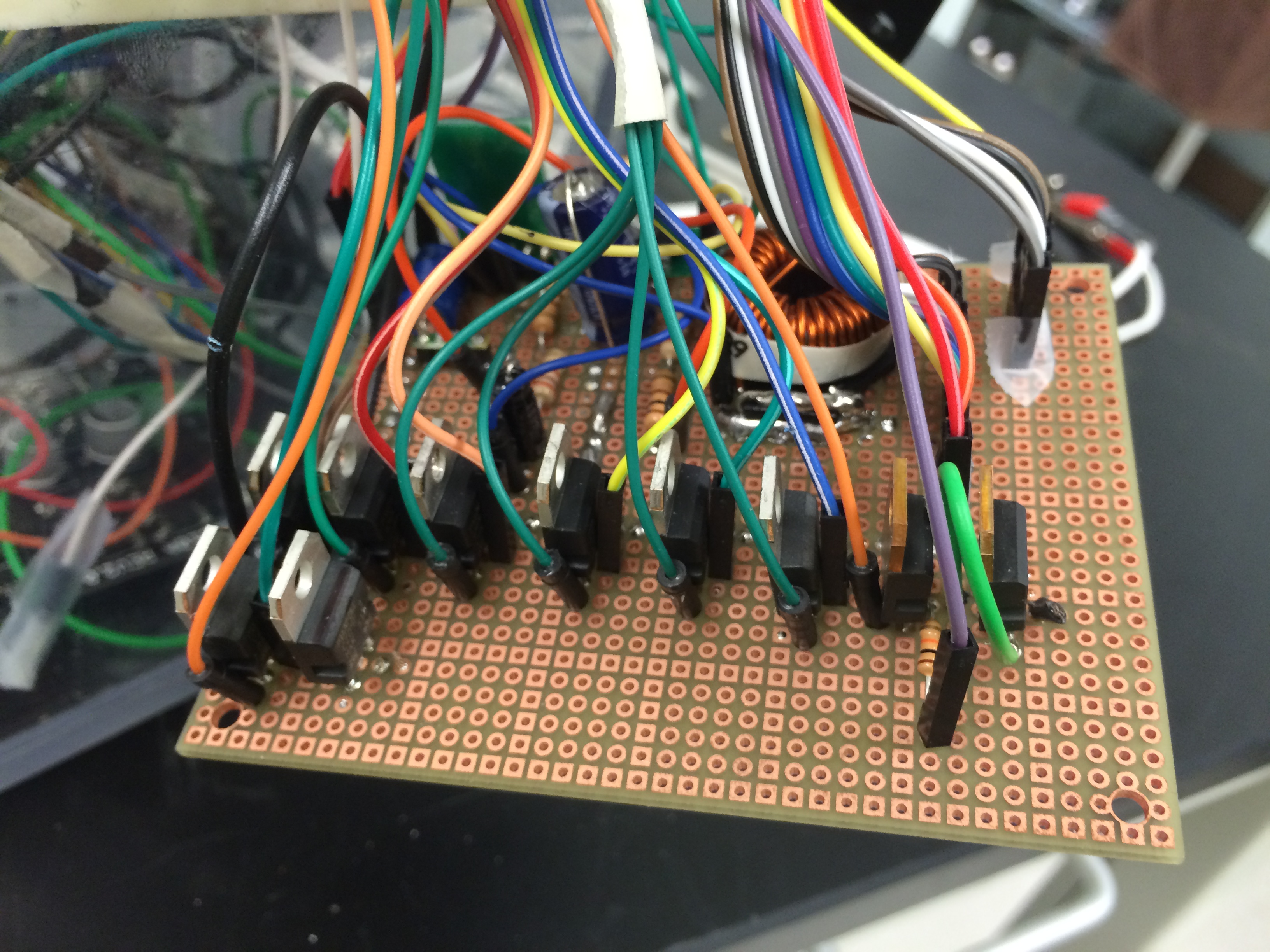
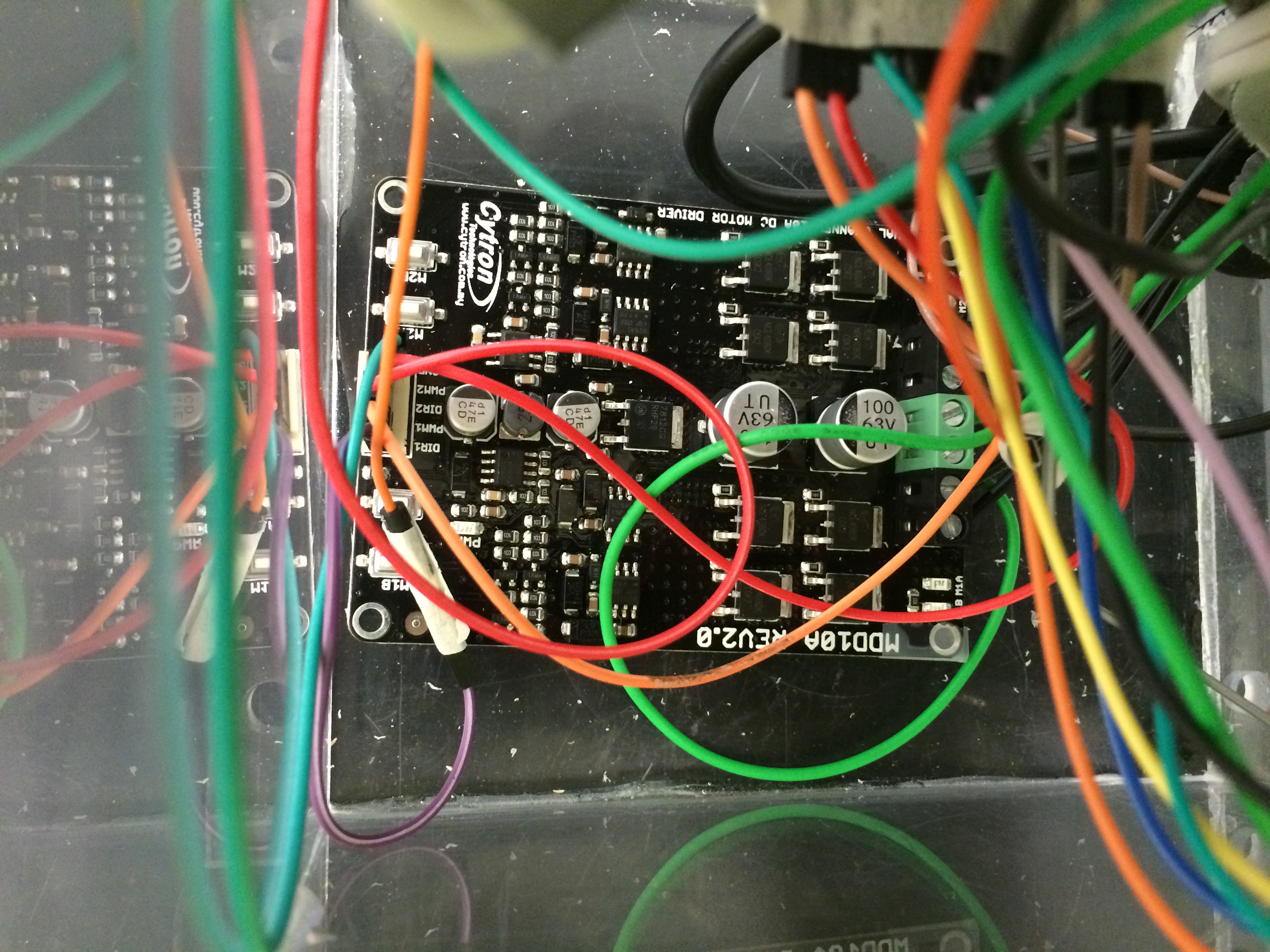
A custom board was made for the power system as outlined in the detailed design section. A 12V 18Ah lead acid battery would be used as the main power supply. The compressor and 4-way solenoid valve could both be run directly off this. The motors were also 12V but required 5A of current which is more than the arduino can supply, so a Cytron MDD10A was used as a dedicated motor control board. The board was still capable of being controlled by the Arduino. The 3-way solenoid valves used 24 volts and the the Arduino and pressure transducers used 5 volts. The input voltage from the battery was regulated to accommodate this using a boost converter circuit. MOSFETs were placed between the drain of the solenoid valves and compressor and the ground. The output from the Arduino was used to control the MOSFETs and actuate the each solenoid valves or compressor. The circuit boards can be seen below.
Boost Converter Circuit and MOSFETs:
Cytron MDD10A Board:
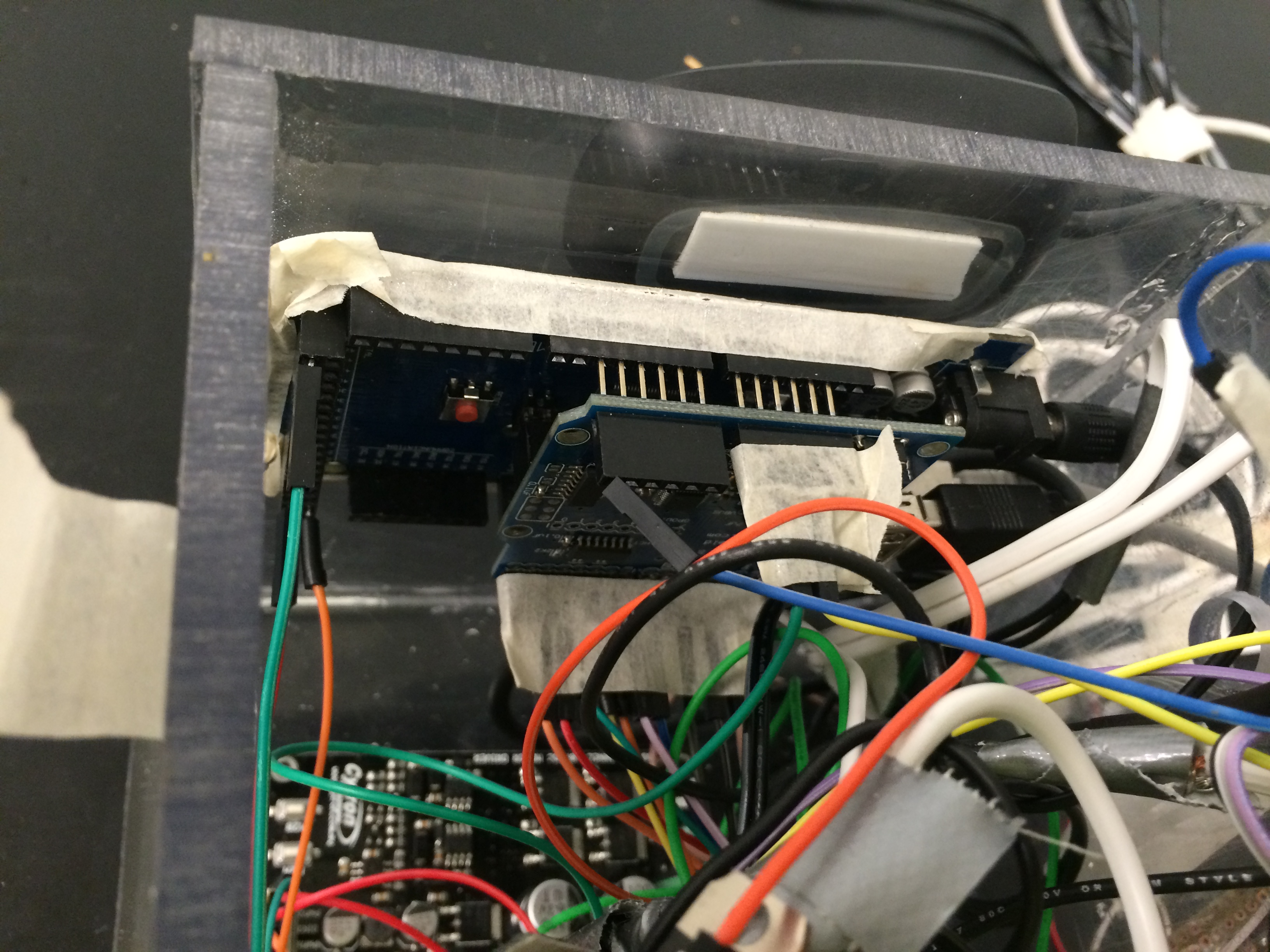
Arduino with Shield, and gaming receiver behind: