Electromagnetic Fin Robot
Overview
The soft robotic underwater robot with electromagnetic actuation was originally developed in a Master thesis of Robert Hennig under the supervision of Alex Beadette and Conor Walsh in the Harvard Biodesign Laboratory.
The unconventional part of the Robot is the electromagnetically actuated fin. Permanent magnets are enclosed in the silicon injection molded fin. Electromagnets inside the rigid main body create repulsive and attractive forces with these permanent magnets. Consequently, the soft tail deforms and bends. An undulating movement of the fin then results in forward propulsion. The tail reaches high undulating frequencies of up to 14Hz, which is significantly more compared to pneumatically driven robots. This results in a swimming speed of 14.3 cm/s.
Overall Body
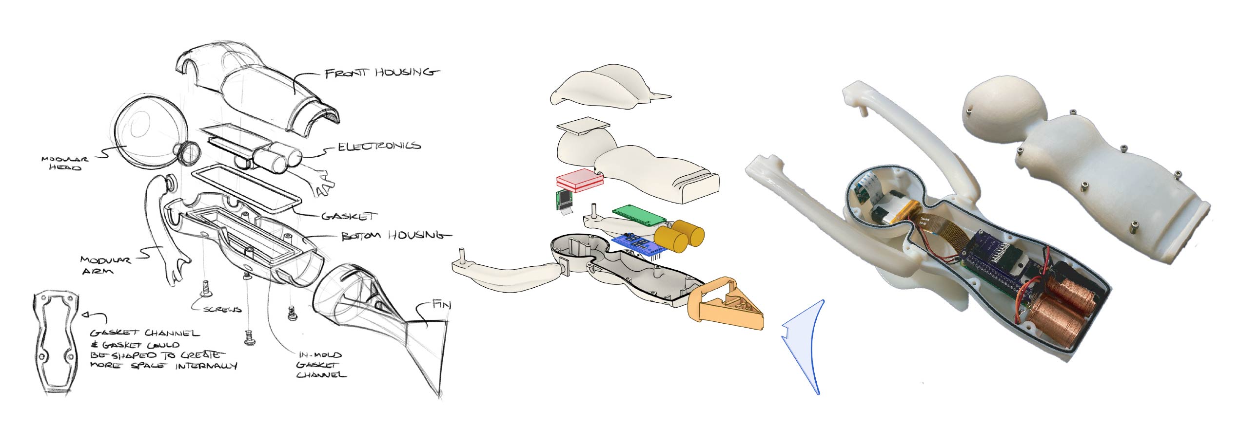
The overall first sketch of the project can be seen in the picture below. The soft caudal tail is attached to the main body using a sleeve, which is part of the silicon cast tail. The main body is a waterproof shell housing the electronics including the electromagnets in the very back. It is important to reduce the distance between electromagnets and permanent magnets to ensure sufficient transmitted forces. On the Main body modular arms and a head can be attached. The passive arm and hair components are designed in a shape, such that their finlike shape enhances the fluid dynamics while swimming. This reduces twisting of the main body caused by the flapping fin.
The two part hull is held together with six screws. Square nuts are inserted into the 3d printed design to enable a proper fastening of the M3 screws. A channel around the inner side of the hull is filled with a gasket. Upon fastening the screws the notch from top part of the hull fits directly into the gasket filled channel creating a waterproof seal.
Weight distribution and buoyancy
The goal is to achieve neutral buoyancy to float steadily at every depth. As there is currently no active buoyancy control implemented. The robot is slightly positively buoyant such that the hair peaks out at the surface, similar to that of a shark. Thanks to that mechanism no active buoyancy control is needed and the robot stays just below the surface.
Additionally to the overall buyancy, the position of the weights inside the rigid shell are important. Placing the center of mass precisely below the center of buoyancy ensures the underwater robot is inherently stable in the water. The center of gravity and buoyancy as well as their respective values were compared and the design adjusted. Additionally multiple mounting places for weights are distributed to fine tune the weight distribution. This includes the tip of the hands to ensure a lower center of mass.
Electronics
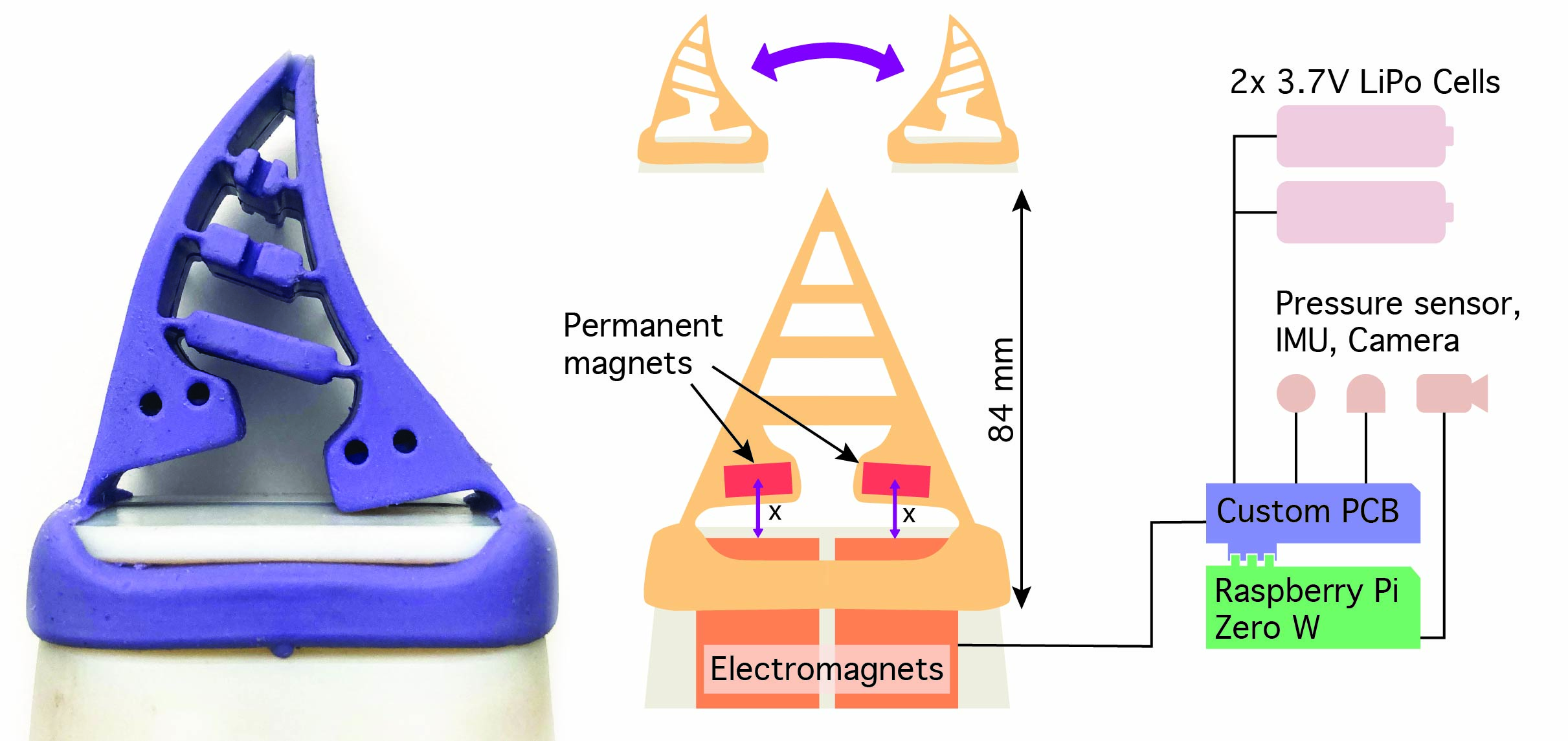
The overall layout of the electronics is can be seen in the picture below. A Raspberry Pi Zero W was chosen as a digital processor. While being compact in size it offers wireless communication, a camera interface and GPIO (General input output pins) pin control making it a clear choice. To enable the Raspberry Pi to interface with sensors and actuators and receive power a custom board was designed, that is mounted on the Raspberry Pi.
The motor driver chip L298N is the main component of the PCB. It drives the electromagnets using the logic input from the GPIO pins of the Raspberry Pi and the direct power of the battery. It supports currents up to 2A for each electromagnet and Voltages up to 46V, which is notably more than the 1A, 7.4V currently used. To power the logic of the L298N chip and the Raspberry Pi the voltage regulator L7805 is used. It provides a 5V output current of maximum 1.5A.
Two 3.7V LiPo batteries are connected in series, resulting in a total voltage of 7.4V. Each of them having a capacity of 850mAh. The two batteries can power the electromagnet drawing 1A at 7.4V for 0.85 hours or 51 minutes.
A 9DoF IMU Breakout board and a pressure sensor (TE Connectivity MS5803- 02BA) can be added to receive feedback during autonomous swimming. They communicate via I2C with the Raspberry Pi and are mounted on the custom PCB.
Electromagnetic actuated fin design and fabrication
As seen in figure 2.1 the actuation idea utilises the simple repelling and attracting force between an electromagnet (EM) and a permanent magnet (PM). The magnetisation of the iron core of the electromagnet is set by applying the corresponding current to the coil, wrapped around it. This results in a negative or positive force between the EM and PM. As no physical connection is necessary to translate the force the electromagnet is placed in a waterproof body housing the electric components. The permanent magnet is placed inside a soft silicone cast tail. By applying a current to the electromagnet the force on the magnet changes. This causes the tail to move accordingly. To create the desired undulating movement two pairs of electromagnets (EM) and permanent magnets (PM) are used.
The successful implementation of the magnetic actuation method was devided into three steps.
• Magnet electromagnet interaction First the EM and PM interaction
• Soft tail design The soft silicon cast tail needs to translate the force of the PM to a strong undulating movement.
• Caudal fin design and control The undulating movement needs to propel the underwater robot forward with significant thrust. A bioin- spired approach is utilised.
Magnet electromagnet interaction
To optimise the force applied at the respective distance to the permanent magnets two things can be improved. The electromagnet (EM) can gener- ate a stronger magnetic field and the permanent magnet (PM) can have a stronger dipole moment. The dipole moment of a PM can be increased by having a higher remanence magnetisation or a larger volume. The volume is constrained to fit inside the soft tail. The magnet material used is N52 grade neodymium which is one of the strongest magnetic materials com- mercially available. The rating corresponds to a remanence magnetisation of Br = 1.48T. For the dimension of the used magnet (r = h = 6.35mm) the overall magnetisation when considering the whole magnet as a single dipole is mmag = 0.947A · m2.
The current and windings of the electromagnet should be maximised to increase its field and consequent force. The limitations include heat distribution and power output of the electronics. The resistance of the whole coil wire is important as it determines the resulting current depending on the applied voltage (I = U/R). The resistance depends on the total length of the wire and the thickness of the wire (re- sistance per distance). Using a thicker wire results in a lower resistance increasing the current when applying the same voltage. However the density of the windings is reduced. This affects the overall magnetic field in opposite ways. Therefore a trade off has to be found. The wire used is the 26 AWG Enameled Copper Wire. It has a diameter of 0.4 mm and a maximum resistance of 141.7 Ω/km.
To estimate the magnetic field and resulting forces depending on the parameters an analytic model is established. The important influence of permeability μ was simplified in the simulation by assuming vacuum with a permeability of μ0 scaled by the factor of the effective permeability μ = μ0 · μeff. As the iron core has low remanence this approximation can be made. Here large imrovements could be achieved in the future. After considering the stated aspects a coil with a soft iron core of 12.7mm diameter, an outer diameter of 22mm and a length of 32mm was chosen.
To fabricate the the electromagnet 3d printed guide rails have been designed (figure 2.2). A guide is placed in the winding setup shown in the figure. Enameled wire is locked on the guide. One hand rotates the setup consistently and the other hand feeds the wire in the correct place. After fully winding the coil the iron core is placed in the center of the guide and con- tacts are soldered. The finished electromagnet is then placed in the underwater robot.

The soft tail design
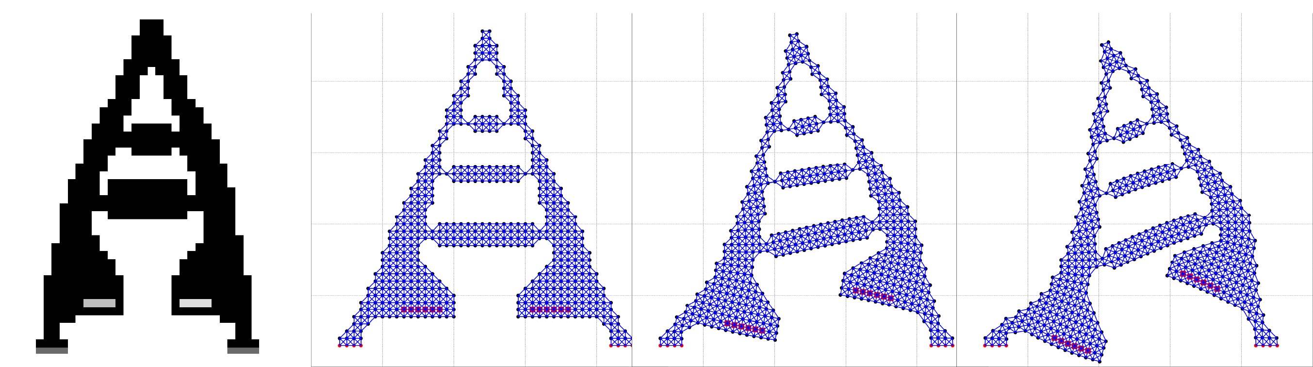
The main task of the soft tail is to translate the force of the magnets into a flapping tail motion. The overall tail design is originally inspired from triangle shaped passive grippers (Fin Ray Effect). Their triangular shaped ladder design causes a bending motion upon a pressure acting on one of its sides. Instead of an outside force causing the bending motion magnets are placed on either side at the bottom of the tail. This allows the permanent magnets to be close to the electromagnets to transmit sufficient force.
Various design alternatives were conceptualised. To estimate the compliant response to the force of the magnet a 2d simulation is developed. The approach is based on a spring network. A low res image with marked pixels is used to define the shape of the structure to analyse. Different brightness values mark rigid areas or areas where forces are applied - eg. the magnets are placed. From those pixels a grid network is determined. Vertical, horizontal and diagonal nodes are connected using a joint. Forces on those joints are iteratively computed and the position adjusted to minimise forces. The underlaying principle is the one of a spring network.
The soft tail fabrication
Three different smooth on materials were explored. While Body Double Silk and Dragon Skin 20 worked the Smooth Sil 945 was chosen as the ideal material due to its higher hardness making a thinner and more precise tail design possible.
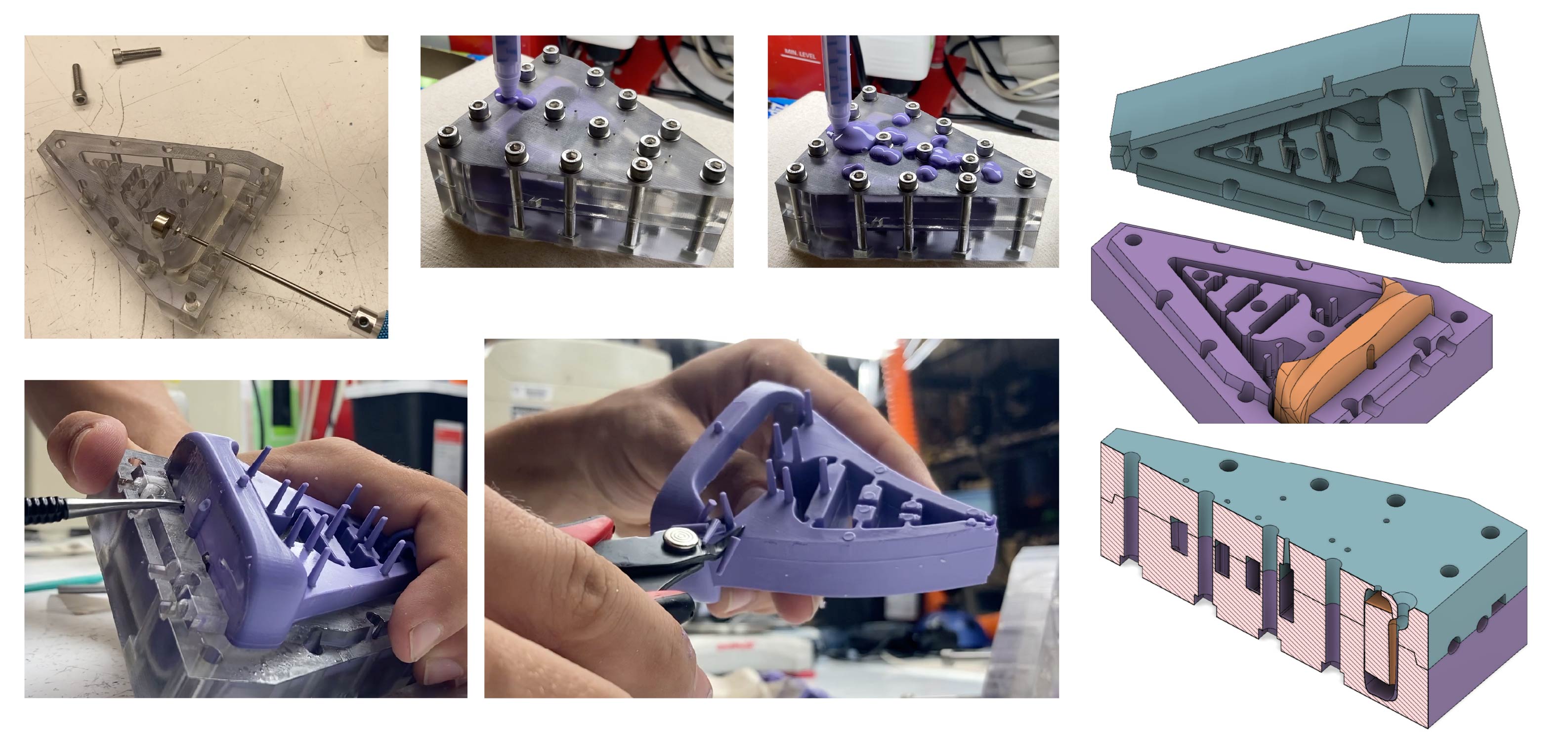
The tail was injection molded. It can create more complex shapes compared to a standard mold. This process is also commonly used in industry due to its convenient workflow once setup, precision and repeatability. As the name injection molding implies, silicone is injected into a cavity. The most crucial part is to allow the air to escape such that the silicone completely fills each cavity. A proper design of the form is crucial to ensure a successful injection molding process. Therefore I list the most important aspects to keep in mind when designing an injection mold. As a reference find images of my injection mold in the figure below.
- Design the desired shape of the tail
- Enclose the tail in a larger rectangular box, leaving extra room for screws around the corners. Then substract the component from the rectangular box to recieve the hollow mold.
- Split the mold to be able to take the silicone part out of the mold after curing. Keep in mind the following things:
- Do not have overhangs in your final parts. Choose the parting line between objects accordingly. Ideally all vertical walls should be drafted slightly (1-3 degrees).
- For some designs a two part mold does not suffice. The overall mold then needs to be cut into 3 or more pieces.
- Make the perimeter of your top and bottom have a drafted lip to ensure self- reliant alignment.
- Use screws approx. every 15-20mm to secure the mold together. Here cutouts for square nuts (M5) were used to be able to fasten the screws well.
- Take into consideration, that due to the examined heat when cur- ing the material can shrink and expand. Therefore it is advised to break all corners on the female mold side.
- Determine a flow concept of the silicone during the injection molding process.
- The material should be injected at the lowest point of the mold. Here a injection port channel can be used to lead to the appropri- ate point.
- Place vent holes at the top part in areas where air gets trapped. They should end at the same height to avoid excessive overflow of material.
The process of injection molding is listed in bullet points below:
- 3d printing the mold and baking overnight at 65 degrees to remove materials inhibiting the silicon later from curing
- Apply mold release to the individual parts to cover all surfaces.
- Assemble the mold and fasten all the screws tightly (there can be high pressures for viscous materials).
- Then a pressurised system established in the Lab was used to inject a homogenous 1:1 mix of two component silicone in the injection port channel. Alternatively a simple syring can be used to manually inject the silicon.Here it is important to apply constant pressure through the whole injection molding process to reduce the formation of bubbles. As soon as all the vent holes start leaking silicone one waits for about another 3 seconds and then stops injecting silicone.
- The mold is then cured according to its specification. To accelerate the process the injected mold is placed in the 65 degree oven.
- After fully curing the part the mold is taken apart and the finished piece removed. Extra protruding vent hole nozzles are cut off.
Caudal fin design
The goal of the whole actuated tail is to create a maximum forward thrust. To achieve this the movement of the tail needs to be translated into a fin stroke. A bioinspired approach is chosen to design the caudal tail. Receiving inspiration from biology makes sense as there are not only millions of examples in nature, but evolution has perfected swimming over billions of years. The shape of caudal fin of a dolphin is cut from a 0.5mm PMMA sheet. It is connected to the back of the injection molded tail, fitting into a specifically designed gap.
Further materials:
Further information can be found in the Master Thesis of Robert Hennig, which is attached to this page. In case of interest for CAD designs and further questions please contact Robert Hennig. (Mail: roberthennig1997@gmail.com )