Fluidic Control Board and Sensor Glove
Fluidic Control Board Design
We used the fluidic control board instructions with some modifications, as our end application projection required variable PSI output based on information we collected. We controlled the PSI through independent pressure regulators rather than using PWM to have a pressure applied and the end of each fingertip. In addition, we added an LCD to help debug code. As for recording data we tried both Flex and Force sensors, ultimately choosing Force Sensors because we did not care about how much the finger bent, but rather how much force is being applied to the pot.
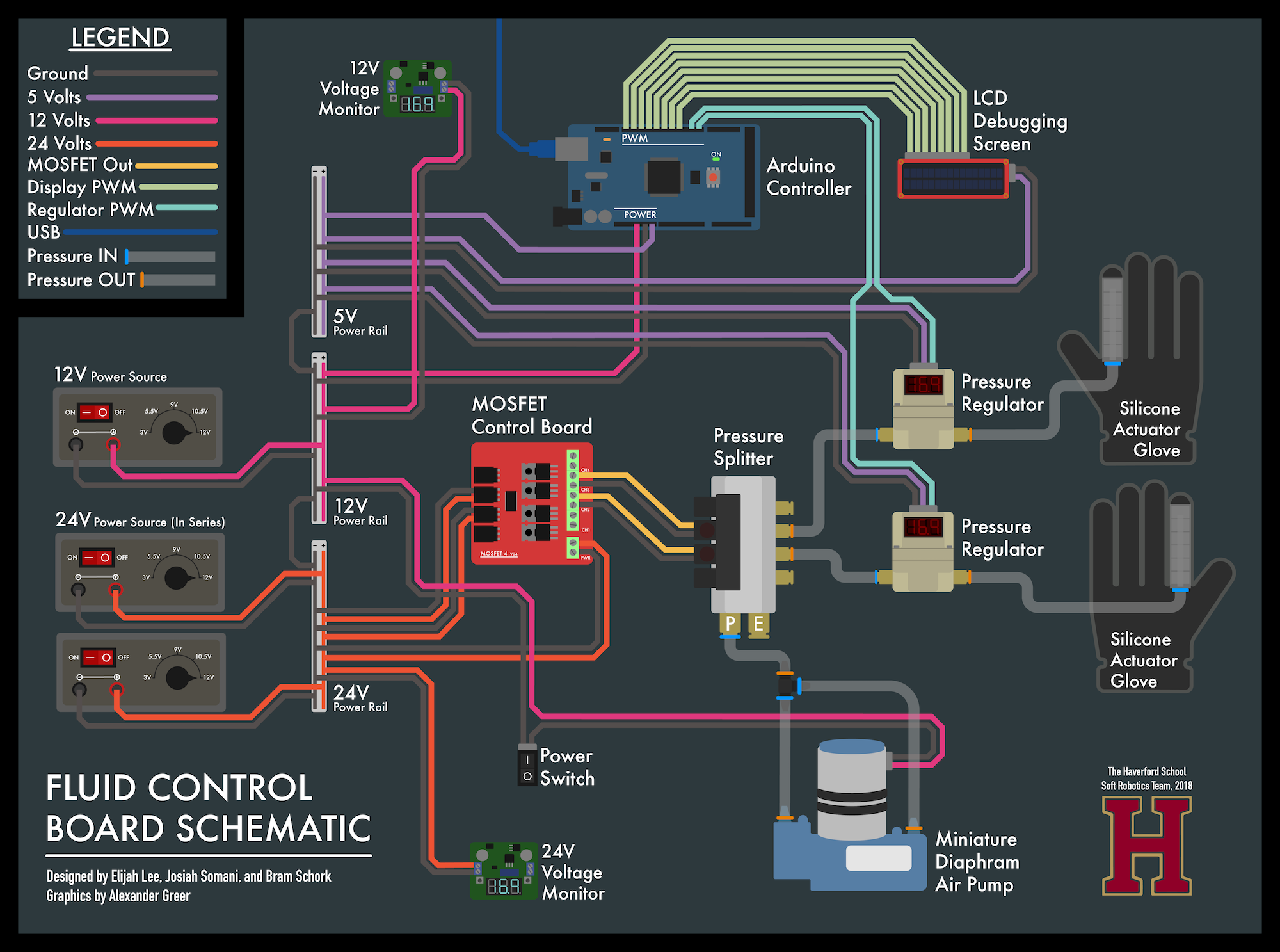
Figure 17: The schematics and circuit diagram of the fluidic control board
Pressure Sensing Glove Iteration
Using the Pressure Sensing Glove we were able to record the hand motions of an articulate ceramicist. Through trial and error, we created a glove that housed the sensor cable robustly such that it would not interfere with data collection. Originally, we used a Flex sensor hot glued on a latex glove. The glue’s bond was poor and broke near instantly. After switching to the Force Sensor we electrical taped the sensor and extension on the exterior of the glove. Worried that contact between the clay and any electrical components could end up being messy and damage the hardware, we resorted to finally stitching all the components to the interior of the glove. In this manner, all components were hidden and we followed through recording our data.

