Problem Definition & System Design
Team Vision for Problem Definition Phase
The project objectives were elaborated in detail to come up with a problem definition which satisfies all parties. Customer interviews were held, and engineering requirements were drafted. House of quality analysis was performed and use case scenarios were drafted.
Project Definition
An Inflatable Robotic Hand is a portable, mountable device that can inflate, manipulate an object, and deflate remotely. The system will be house in a container mounted on a RC car. This device will utilize some of the same principles, specifically the air muscles, used in previous RIT senior design projects P14253, P09023, P08023, and P08024. This project will add the ability of inflating out of a small container.
The goals of this project are to analyze previous air muscle designs, and other inflatable robot technologies, to identify an opportunity to combine these ideas into one product. The expected results is a functional prototype that can be applied to the task. The prototype must use air for generating actuation forces while resembling a hand with a minimum of three fingers.
Use Case
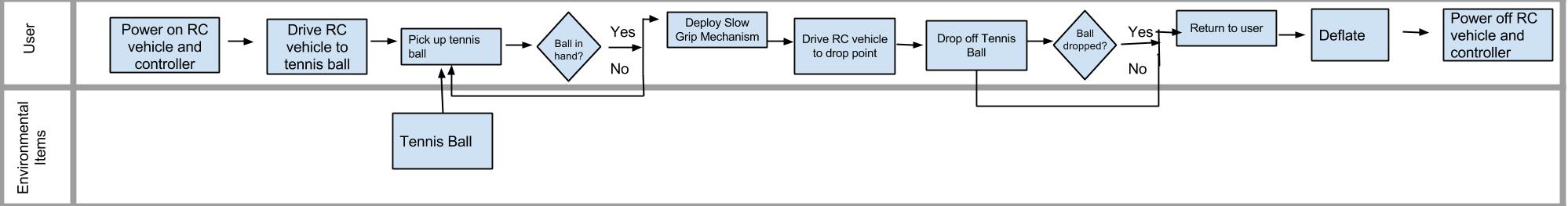
Project Goals & Key Deliverables
- The arm, hand, and vehicle can be remotely controlled by user
- Pick up a tennis ball
- Mounted on an RC vehicle
- Inflate out from a compartment
- Actuation force is produced by air muscles
Customer Requirements (Needs)
Purpose
To decompose the Problem Statement into functions of elements needed to satisfy the customer.
Customer Requirements
Rqmt # | Importance | Description |
C001 | 9 | Must use air for inflation and actuation forces |
C002 | 9 | Must be able to pick up a tennis ball up to 2 in off the ground |
C003 | 9 | Must resemble a hand or fingers |
C004 | 9 | Must inflate from a container housed on an RC vehicle |
C005 | 3 | Must deflate fully back into the container |
C006 | 9 | Must be remote controlled |
C007 | 9 | Material selection must withstand inflation/deflation cycles without popping or tearing |
C008 | 3 | Use a single controller to control both the robotic arm and the RC vehicle |
C009 | 3 | Prototype and final model must be built with a $750 budget |
C010 | 3 | Move object (tennis ball) from one location to another |
C011 | 1 | Mounted camera for targeting and navigation |
Inputs
- PRP
- Problem Statement
- Customer Interviews
- Art North & Dr. Lamkin-Kennard.
Outputs
Engineering Requirements (Metrics & Specifications)
Purpose
Create a contract between the engineer and the customer where indisputable satisfaction of the engineering requirements equates to customer satisfaction
Engineering Requirements:
Rqmt # | Importance | Engineering Requirement | Unit | Target Value | Marginal Value |
001 | 1 | Air compressor power | psi | > 120 | 100 |
002 | 9 | Air compressor flow rate | scfm | > 0.88 | 0.3 |
003 | 9 | Inflation time | sec | < 2 | 5 |
004 | 3 | Deflation time | sec | < 10 | 15 |
005 | 3 | Inflation arm reach | in | > 6 | 4 |
006 | 1 | Object lift distance | in | > 6 | 4 |
007 | 9 | Hand grip strength | psi | > 20 | 15 |
008 | 3 | Stored air volume | ml | > 1200 | 200 |
009 | 3 | Stored air pressure | psi | < 100 | 80 |
010 | 9 | Number of fingers on robotic hand | units | = 3 | 3 |
011 | 9 | Battery life | min | > 90 | 30 |
012 | 3 | Chassis load weight capacity | lb | < 40 | 120 |
013 | 9 | Chassis surface mount area | in^2 | < 24x24 | 30x30 |
014 | 3 | Arm container cross-sectional area | in^2 | < 6x6 | 8x8 |
015 | 1 | Arm container height | in | < 8 | 10 |
Inputs and Source
- PRP
- Dr. Lamkin-Kennard
- Art North
Outputs and Destination
- HoQ
Constraints
From Customer Requirements
- Inflation mechanism must use air only
- Robotic arm and hand must fit inside a small container
From Engineering Requirements
- Weight of robotic arm, air compressor, tank, and control systems must not exceed chassis weight capacity
- Must have large enough power source to supply power to the motors, compressors, and control systems
House of Quality
Inputs and Source
- PRP
- Customer Requirements
- Engineering Requirements
- Benchmarking Data
Outputs and Destination
Design phase
Team Vision for System-Level Design Phase
Our plan was to develop the functional decomposition of our system, come up with possible solutions, and out line the system architecture. We also planned on benchmarking the different components and analyzing the feasibility.
We were able to complete all of the tasks we set forth to do for this phase.
Functional Decomposition
Benchmarking
Morphological Chart and Concept Development
Concept Selection
Concept Selection & Pugh Chart