Design
Included Designs
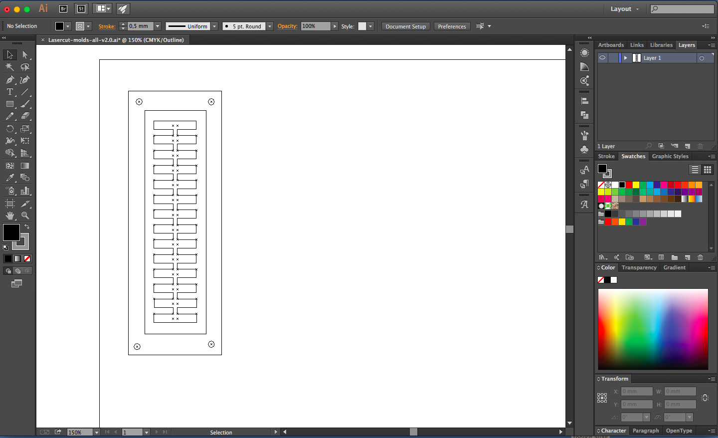
The design files were created in Adobe Illustrator by aggregating shapes drawn with the Line and Ellipse tools. The designs are saved as a vector graphics file that can be used with a laser cutter. Molds for four different bending actuators are included - a leaf shape, a triangle, and two rectangles:

Screen shot of the design file opened in Adobe Illustrator
Each actuator mold consists of a top, middle, and bottom part that are laser cut in acrylic and subsequently glued together.
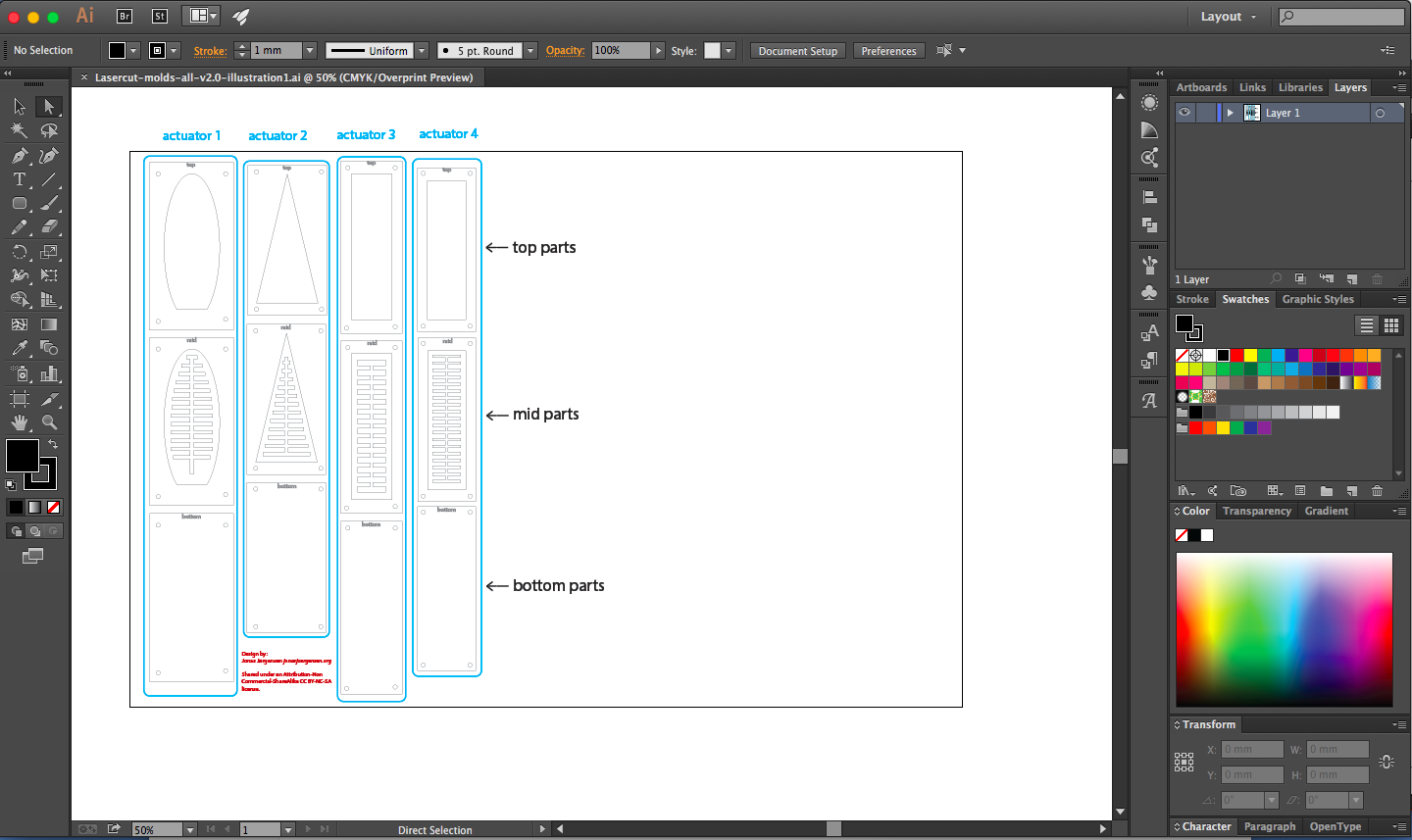
The arrangement of the parts for the molds for the four different bending actuators.
To create the leaf shaped mold, for instance, the parts marked in blue below are used:
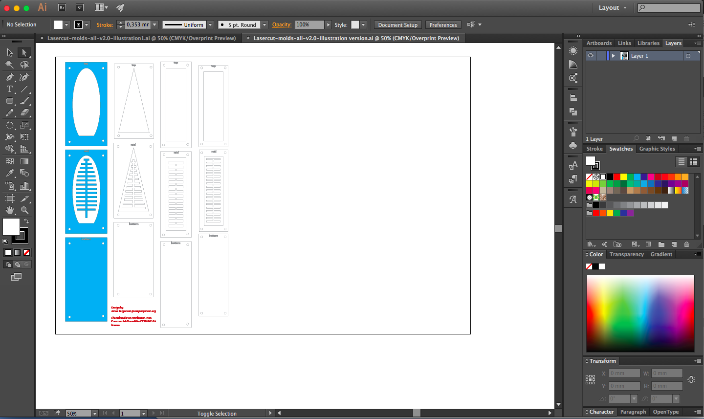
The mold parts for the leaf shaped actuator.
Design Procedure
The following procedure was used to generate the included design files for laser cutting molds.
First the shape and dimensions of the actuator is decided upon based on its intended usage (see e.g. this publication and this publication).
To draw the design for a mold, it is easiest to start with the fishbone structure that generates the interior compartments of the pneumatic networks. The Line tool automatically gives the length of the line drawn, which makes it easy to use for this purpose.
Select the Line tool and choose a stroke width that is interpreted as a cut line by the laser cutter (usually below some threshold e.g. 0.1pt.). Start by drawing the two first compartments and the channel that connects them:
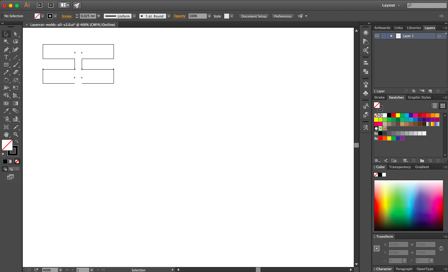
After this, select the 8 line segments that make up the bottom compartment and the channel (shown in blue below):

Make a copy of them and place the copy below the two compartments to make a third compartment (shown in red below):

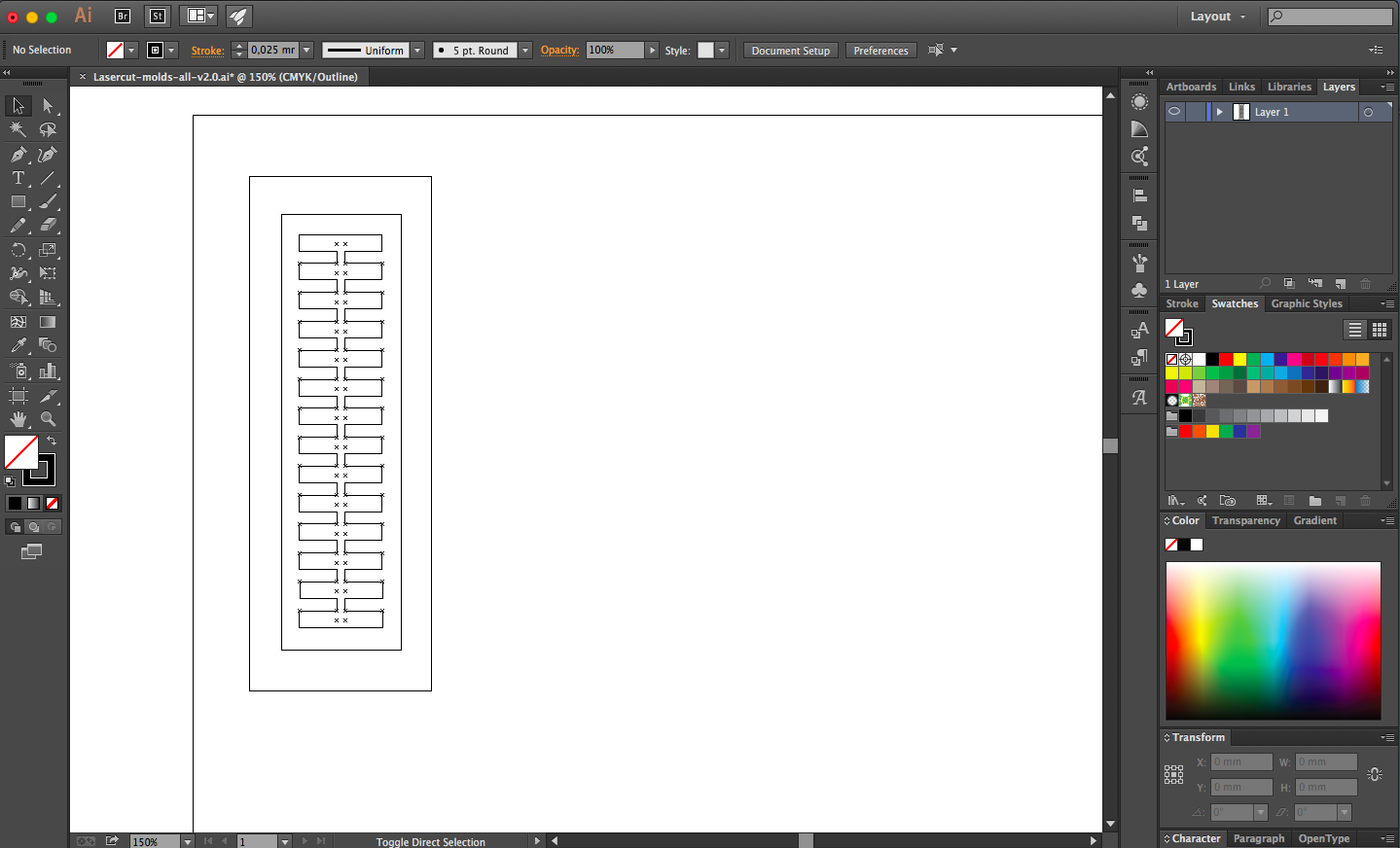
Continue in this fashion by selecting and copying compartments and channels until you have the amount of compartments needed (Note: Select and copy multiple compartments and channels once you have generated more of the structure). Finally, the bottom compartment can be generated by copying the top compartment and channel and rotating them 180 degrees. With this compartment in place, the fishbone structure is complete:

After the fishbone strucure has been drawn draw the outline of the actuator and the mold (e.g. with the Rectangle tool):
Add holes for screws (using the Ellipse tool):
Now make two copies of everything drawn so far. Delete elements in each of these to make the designs for the top and bottom mold parts:
Save the finished design in a vector graphics file format e.g. .ai, .pdf, or .svg.
Contributors
Jonas Jørgensen