Proof of Concept and Testing
Proof of Concept
A prototype of the underwater glider was built and proofed the design concept as feasible. As it can be seen in the video below, the soft actuator undulates in a waving motion as predicted. Attached is a video of the soft actuator being tested by hand pulling the steel cable.
A full prototype of the underwater glider is assembled and is displayed in the image below:

Each subsystem when tested independently were successful as they were able to perform each of their specific tasks, shown in the next two subpages of this section. However, when both subsystems are assembled and the steel cables are screwed into the propulsion system, the system failed to perform properly. One of the possible reason of failure was that the 28BYJ-48 12V stepper motor couldn't handle the force required to pull the stainless steel cables. The failed run can be seen in the video attached below.
Testing
Testing procedures are proposed to get an accurate representation of the AUV’s response to the control inputs. A preliminary method of testing was done by acquiring an underwater glider model in matlab that is adjusted to our glider’s parameters and is shown in Figure 4 below. A force analysis of all of the critical components was also done to assure that these parts will not fail and to see if the expected maximum torque and power rating that is needed is met for each motor.
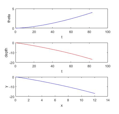
Theta, depth, and path response simulation example of glider.
Future testing procedures to consider is the use of two accelerometers that will be used to study the relationship between the side to side movement of the tail and the forward velocity of the glider. First an accelerometer is embedded inside the tail fin of the glider. This accelerometer is used to measure the position, velocity, and acceleration of the tail fin. The second accelerometer is placed inside the glider body of the AUV. This accelerometer measures the position, velocity, and acceleration in the forward direction of the glider. By using these two accelerometers a better understanding of the position and movement of the glider was developed. By gathering the actual state response of the AUV, the previous model will be adjusted accordingly for more accurate predictions of state estimates.
The simulation model of the AUV is performed using matlab simulink, where the differential equations of the states of the AUV are solved using matlab’s ode45 solver and initial condition. Theta in the graph above indicates the angle of attack that the glider takes with respect to the x axis.
Last method of testing as proof of the fin’s improvement to the glider’s maneuverability is by running the AUV through a predetermined course with checkpoints to see how long it would take for a control glider, and the improved version to go through all checkpoints.