HPN Manipulator
|
The hexagonal comb of the honey bee (honeycomb) can provide material with minimal density, high compression properties and shear properties. This structure is widely used in aerospace industry like aircrafts and rockets. Thanks to these properties, we use honeycomb structure to provide a skeleton for inside pneumatic networks and stable support for the whole manipulator. Pneumatic networks are a series of channels and chambers inside an elastomer, which are rapidly responsive and environmentally benign. Moreover, they are cheap, accessible and easier to fabricate than traditional rigid actuators. |

|
Because most soft manipulators lack strength, this largely undermines their possibility in practical use. We aim to design and fabricate a soft manipulator with a relatively large load bearing capacity. We embedded pneumatic networks into a honeycomb structure skeleton, balancing advantages from both, to build a powerful, stable and flexible manipulator.
|
|

|
To get better understand of this structure, we use Finite Element Method (FEM) to analyze the mechanical properties and improve the performance by changing geometric variables. After that, we validate the result with a physical prototype. |

|
This documentation set contains files and instructions to support the design, fabrication, modeling and testing of a HPN manipulator. We also provide a case study of this manipulator's potential in practical use. Moreover, the modeling result can be the guideline for the fabrication of HPN manipulators to satisfied different requirements in practical senses.
|
|
Design
Inspiration
Honeycomb structures are masses of regularly arranged hexagonal prismatic wax cells constructed by honey bees in their nests for containing their larvae and storing honey and pollen.
| A honeycomb shaped structure can provide a material with minimal density and relative high out-of-plane compression and shear properties. Engineers have applied the honeycomb structure to numerous engineering and scientific applications. |

|
Inspired by the honeycomb, a novel structure coined 'honeycomb pneumatic network' was esablished as part of this actuator. Honeycomb has the property of high elongation rate and crush resistance, while the pneumatic networks system is lightweight, rapidly responsive and environmentally benign. HPN combines these properties by placing pneumatic units inside the honeycomb-shaped structure.
Design overview
|
The HPN manipulator documented here consists of a honeycomb-shaped frame and a series of pneumatic networks arranged within. The manipulator can be constructed upon several segments with different parameters. Each segment contains four pneumatic network groups, each consisting of 8 chambers connected consecutively. These pictures show an overview of single segment of HPN manipulator and it's deformation in two different directions.
|
|


Honeycomb Structure
Design parameter
For the same material, different structures can make vast difference on mechanical properties.

Specifically, for a single honeycomb chamber, the figure above illustrates the difference of deformation about different wall thickness and with the addition of grooves under the same pressure and cross section area. The structure with a thicker wall appears are more stable however the addition of the inner grooves imparts additional flexibility to the structure.
Thus, we use flexibility and load bearing capacity as the evaluation metrics of mechanical property of the HPN manipulator. Flexibility is defined as the ratio of the reachable area of the manipulator's tip to the square of manipulator's original length. And load bearing capacity is defined as the maximum load moment under the condition that the manipulator's tip can hold stably at the same height with its fixed end. The definitions have relations with the original length of the manipulator, however, the connection can be approximately omitted.
Later, we will illustrate the model design procedure and use FEM simulations to estimate the relationship between flexibility, load bearing capacity and wall thickness, as well as groove depth. The result can be viewed on the testing page.
Honeycomb structure
|
The honeycomb structure we use to make manipulators consists of compressed hexagonal chambers. This structure has many advantages, such as a high elongation rate and crush resistance, When airbags inside pressurize, some of the chambers deform, so the structure elongates or bends.
Before making our model we must determine the design parameters. There are several dimensions that affect the actuator’s behavior: wall thickness, and groove depth.
|
|


Model design CAD tutorial
This tutorial contains step-by-step instructions for making a solid model of a Honeycomb structure in SolidWorks 2015. The SolidWorks part files can be downloaded here. If you prefer to use a different software package, you should be able to apply the general tutorial steps to most solid modeling environments or you can refer to the dimensioned figures below.
In addition, there are other design parameters to be determined: chamber height, and overall number of chambers.
In this tutorial we will make an honeycomb structure with 2 columns, each column have 8 chambers. Each chamber is 3.5 mm long, 39 mm wide, 60 mm high, with 2 mm wall thickness. Of course, you can alter these parameters to change the morphology of your actuator yet general steps covered in the tutorial should still apply.

Design Individual Chamber
There are many ways to make the honeycomb structure, in order to make it easy we will introduce it here step-by-step.
The general overview of steps entails first creating a fragment of one chamber, and complete it using symmetry operations. After that, the whole manipulator can be achieved by replication based on one chamber and patterning to achieve the network.
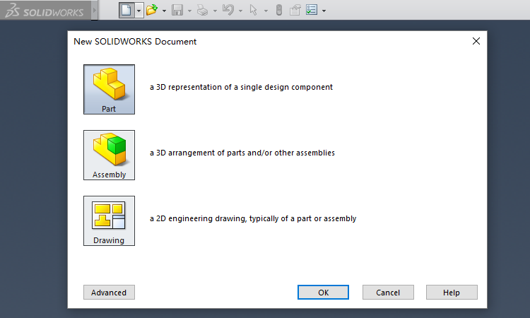
First step, launch Solidworks and create a new Part.
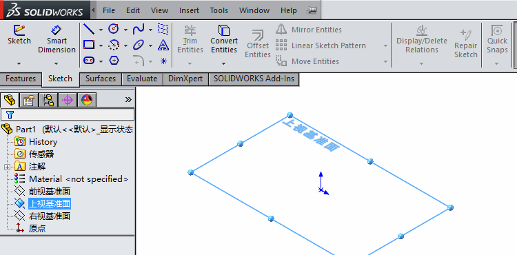
Next, select a datum plane and begin to sketch.
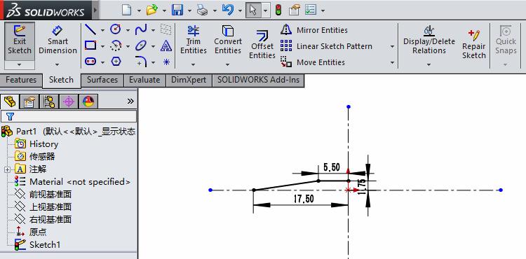
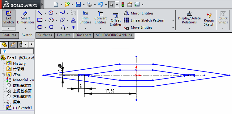
Next, we draw the sketch of a single honeycomb chamber. Because the chamber is a symmetrical hexagon, we only draw its quarter and then mirror it twice (using the Mirror Entities operator).
Now it's the sketch of one quarter of the hexagon shown below.
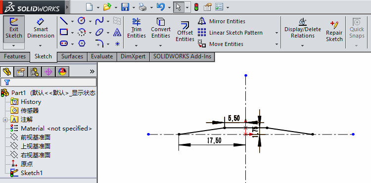
Mirror it for the first time, and we get the upper half of the hexagon.
Mirror again, and we get the whole hexagon.
Then, we use the Offset Entities operator, with the distance of 2 mm, to get the chamber with desired thickness.
Groove on the Corner
As discussed before, there are two parameters affecting the mechanical property of the manipulator: wall thickness and groove depth of the honeycomb structure. In this step, we will implement 2 mm depth grooves in sketch.
Below is the single chamber finished in last step.
We draw a rectangle with a depth of 2 mm and a width of 0.4 mm at the inner acute angle.
Then we obtain grooves on two sides using the Mirror Entities operator.
Pattern Sketch
The manipulator frame is composed of two lines, with 8 chambers on each line. In this page, we show how to sketch that using Linear Sketch Pattern and Move Entities operators.
Here is the sketch of a single chamber with inner grooves finished in last step.

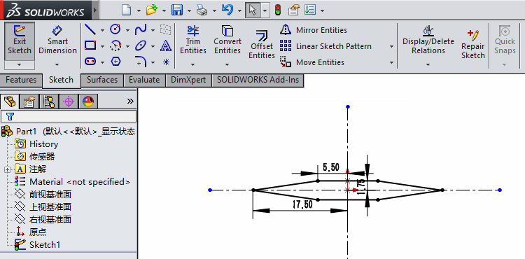
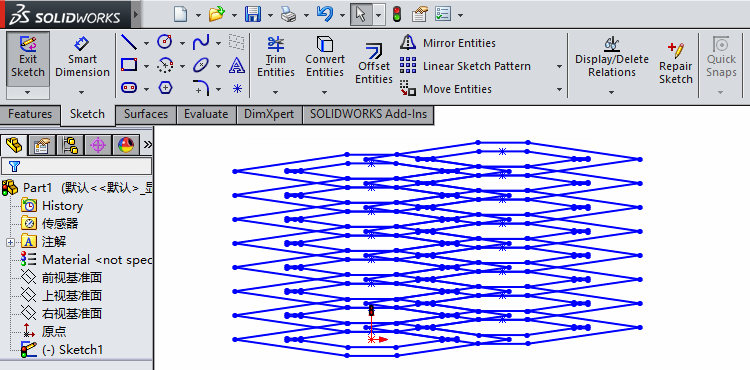
We use Linear Sketch Pattern operator and pattern it as below, with instances as 8 and spacing as 5.5 mm.

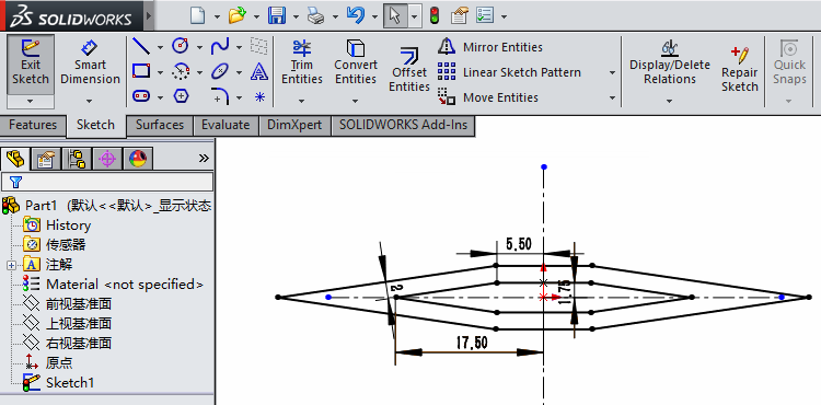
Click Accept (green check mark on the left), and finish the pattern. The result is shown below.

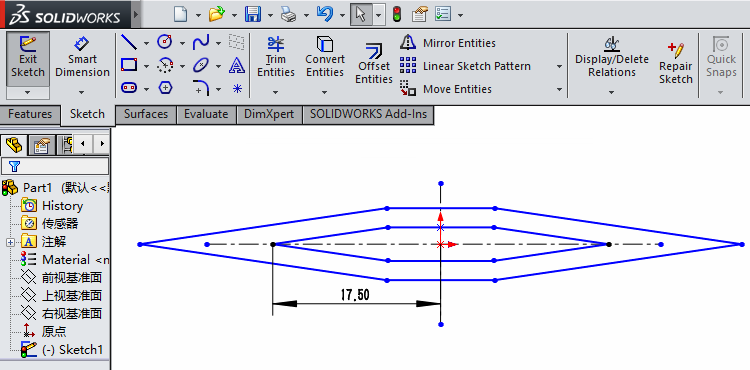
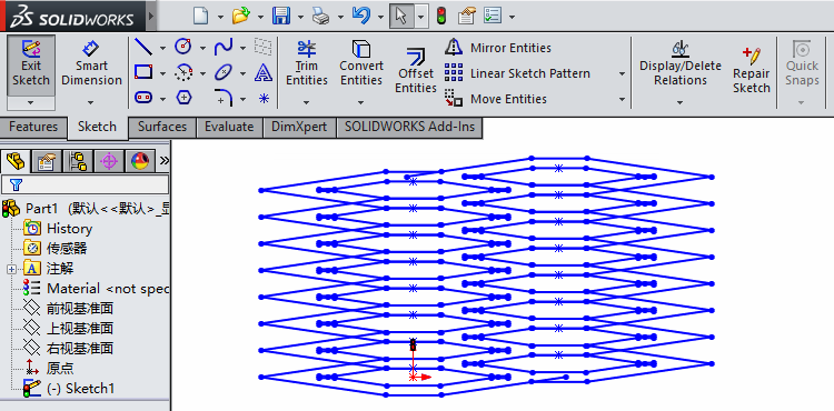
Then, enable Move Entities operator, and select start point and end point at the red points shown below.


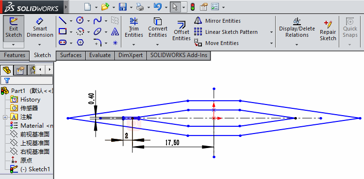
Click Accept, and get the sketch below.

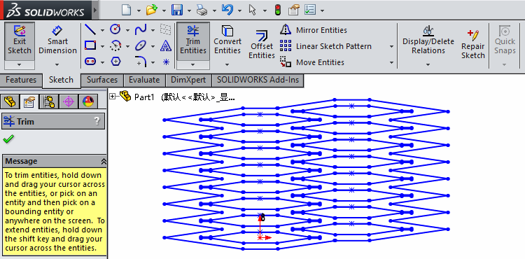
Trim
In this page, we trim the sketch using the Trim Entities operator based on last step. The result will be used for extrusion later.
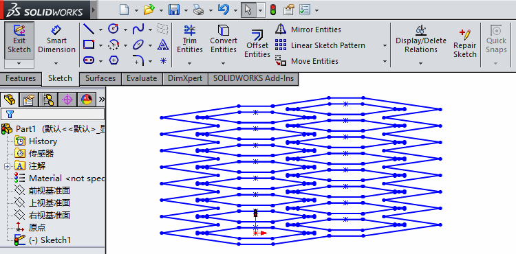
As shown below, we have drawn the sketch of the whole honeycomb structure.
First, select redundant lines and delete them by clicking delete button on the keyboard. We need mention that the two lines on the upper and lower boundaries cannot be directly handled in this way.
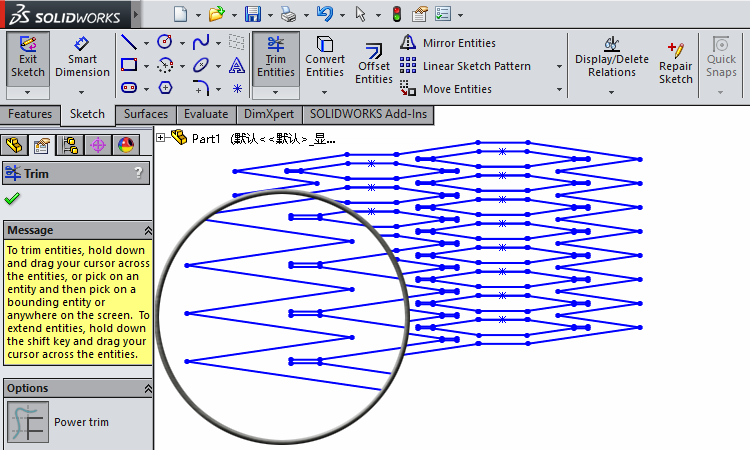
So we use Trim Entities operator to cut the extended area on the two lines at boundary.
Then, we also use Trim Entities operator in order to cut the redundant lines at the inner grooves, which can be observed in a magnified view.

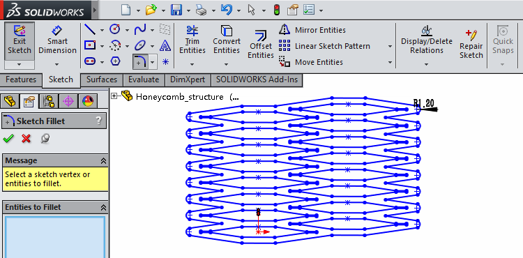
At last, we use Fillet operator and smooth the structure's two edges as seen below.
Extrude
In this page, we illustrate the procedure of obtaining a 3D structure using the Extrude command.
The figure below is the trimmed sketch from last step.
We select Extruded Boss/Base command in 'Features' panel, and select the colored area in the figure below.
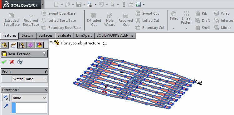
Set the height as 60 mm.
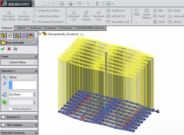
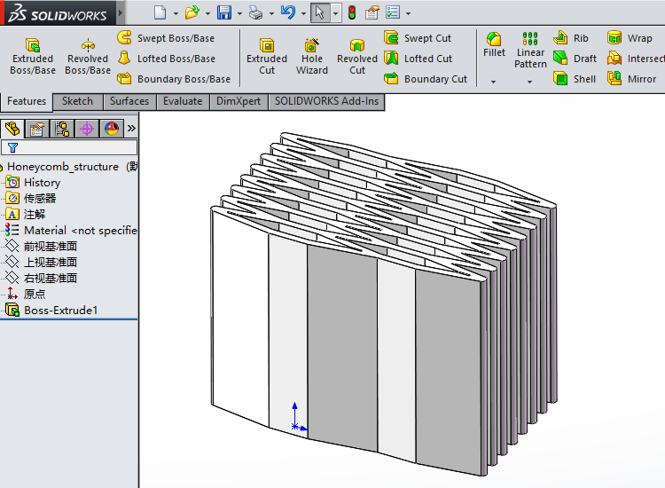
Click Accept (green check mark) and get the final 3D honeycomb structure.
Pneumatic Networks
|
The pneumatic network is an important part of HPN manipulator. In this section, we will introduce an innovative design of this proposed pneumatic network. |

|
|
Conventionally, when we talk about the pneumatic network, the first idea is a series of chambers connected together through specific designed channels (click here to see an example). This is a bottom-up way to build the whole structure from fragments. In the following paragraph, we will introduce the method in which to construct the pneumatic network, which is low cost and durable. The main part of pneumatic network we put here is air columns bag made of PA/PE, which has many advantages listed as follows:
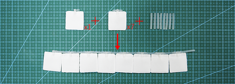
In order to make it easy to assemble the pneumatic network with the honeycomb structure, a column of airbags is divided into 16 individual chambers (as shown in the picture) by heat-sealed tortuous channels. Picture (B) shows the details of measurement and the design of two ends. 16 chambers can be divided into 8 segments, with every two adjacent segments connected through a long tortuous channel with a long air tube inside. Similarly, every two chambers in the same segment can be connected by a shorter tortuous channel with an air tube inside. For the air inlet, we use a straight connector to make it easy to inflate the pneumatic network. When assembling this pneumatic network with honeycomb structure, we can fold the pneumatic network from every short tortuous and plug it into every single chamber of honeycomb structure. The resulting AutoCAD files can be downloaded here. |
|
|


Modeling
As mentioned in design section, wall thickness and groove depth in the design of the honeycomb structure can affect the mechanical performance of the manipulator. In this section, we propose two evaluation metrics for assessing the mechanical property of the manipulator, flexibility and load bearing capacity. After that, we use FEM modeling method to analyze this metric for segments with different thickness and groove depth, which can provide guidance for implementing a real manipulator.
For the whole manipulator, the flexibility is imperative for its front portion of the manipulator while the load bearing capacity is imperative at its base. By comparing the performance of different structures in simulations, we are able to understand the relationship between the performance (flexibility and load bearing capacity) of the manipulator and design parameters (wall thickness and groove depth).
|
|
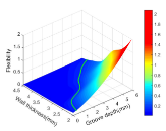
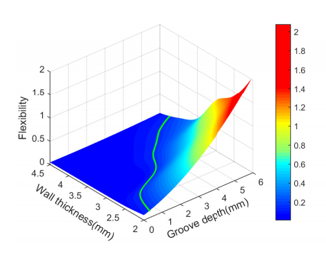
The variation of flexibility is illustrated in the figure above (left). We find that as the groove depth grows, the flexibility increases, while as the wall thickness grows, the flexibility decreases. Both variations are monotonous.
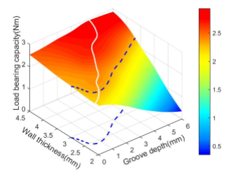
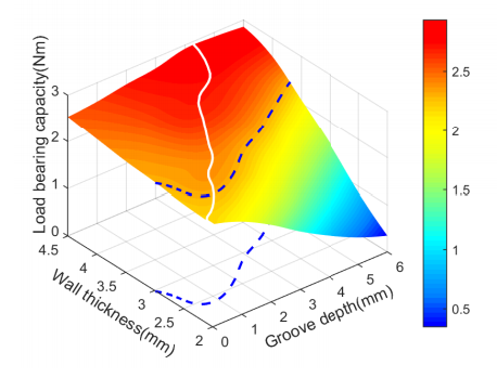
As shown in the figure on the right, the load bearing capacity increases monotonously as the wall thickness grows. However, the variation of load bearing capacity about the groove depth is not monotonous: it initially increases, and then decreases.
All of this will be detailed in evaluation, FEM simulation process and resulting analysis of the parts.
Evaluation
There are kinds of soft manipulators that achieve appreciable performance in their specialty respectively, nevertheless, there isn’t a universal evaluation criteria for assessing and comparing their performance. In this page, aimed at reaching a high level of load bearing capacity with little loss in flexibility, we set these two characteristics as the main metrics.
Flexibility
As for flexibility, we define it as a manipulator’s reachable space, which consists of all the points that the tip of the manipulator can reach with another end fixed. To show comparison between manipulators with different shapes and scales, we calculate the ratio of that space to the dimensionality’s power of its original length, as a relative flexibility.
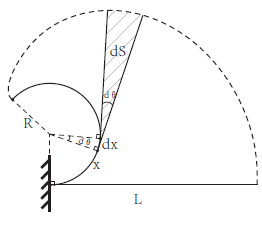
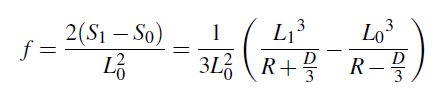
Minimum bending radius, original length, maximum length and width of the manipulator are represented as R, L0, L1 and D respectively. S1 is the bending arc and outer boundary and S0 is the bending arc and inner boundary.
Load bearing capacity
As for load bearing capacity, we define it as the maximum load moment of a soft manipulator when it is able to remain stable and its loaded end is on the same height with its fixed end. How the manipulator reaches such a condition is not confined.
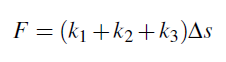
F represents the internal force provided by the airbags, which is determined by the contact area S and pressure p. k1, k2, k3 represent the spring coefficients, M represents the load moment provided by this structure. To reach a balance, we assume a elongation of Δs for the springs.
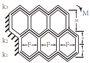
The force balance can be represented as:
The load moment can be calculated as:
Finite Element Modeling (FEM)
This section describes how to perform Finite Element Method (FEM) analysis of our PneuNet actuator using the Abaqus software suite.
Overview of model components
-
2 materials:(because wo notice at structure,so material can be imprecise)
- frame: polyflex density of 1200Kg/m³,a Young’s Modulus of 0.1 GPa and a Poisson’s ratio of 0.38
- airbag: PA+PE density of 1200Kg/m³,a Young’s Modulus of 1 GPa and a Poisson’s ratio of 0.45
-
2 sections:
- frame(uniform solid), assigned to the frame
- airbag (uniform shell), assigned to airbag
Overview of FEM steps
- Import parts
- Assign material properties to the parts (create materials, assign materials to sections, assign sections to parts)
- Assemble parts
- Create step
- Create a universal contact
- Create set and surface
- Apply loads and set boundary conditions
- Mesh part
- Create mesh and run job
Abaqus units
When the lang unit is 'mm' ,the other unit is detemined

FEM for Load Capacity
In this section, we are mainly concerned with the impact of groove depth and wall thickness on the load.
3 loads:
- Step-1: pressure and concentrated force
- Step-2: a contrary concentrated force
So, we can finally get the side of the airbag when fully Inflated, the arm can maintain the level of the load.
Then wo can get the load moment which represents the load capacity of this structure.
Cae here
Import Parts
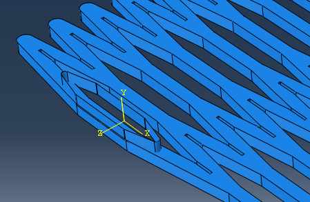
In this project, as mentioned in the Design section, we only consider the characteristics of the manipulator in x-y plane. And thanks to the structural property, we only analyze a slice of the frame (as shown below) instead of the whole structure, which can make the simulation much less computationally expensive.
The .stp files of the simplified geometry used in this tutorial can be downloaded here.
Import frame
To import the fram go to the model tree in the left sidebar, right-click on Parts and select Import. Browse to the frame.stp file. The frame here has a little difference from the CAD tutorial model: the chambers' number is 64 instead of 16, and the extruded height is 2 mm instead of 60 mm.
Create airbag
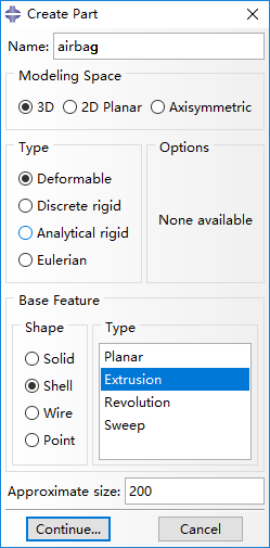
Create a new part named 'air bag' and select Shell and Extrusion.
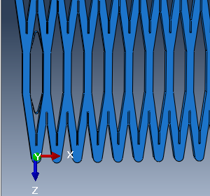
The slice of a airbag should be with an ellipse shape, but we design the airbag as illustrated below for convenience of adding interactions (mentioned later).
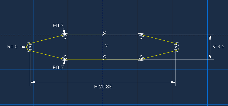
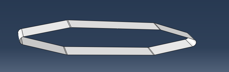
Set the Depth of this extrusion as 20 and the part of airbag is shown below.
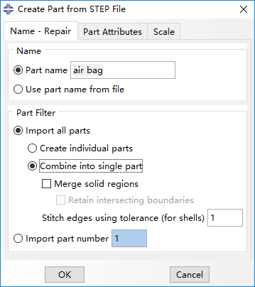
You can also directly import the part from .stp file and select Combine into single part.
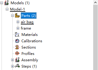
Finally, two parts should now appear in the model tree.
Assign Properties
In this page, we will show detailed procedures of assigning material properties for frame and airbags.
Create Material: frame
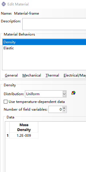
Firstly, we create a new material named 'Material-frame' for the frame. And set the following properties:
-
General > Density:
- Density = 1.2e-9 Mg/mm³
-
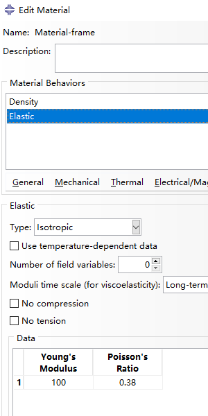
Mechanical > Elasticity> Elastic:
- Young’s Modulus = 100 MPa
- Poisson’s ratio = 0.38
|
|
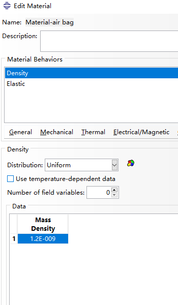
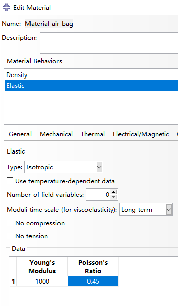
Create Material: airbag
For the property of airbags inside named ' Material-air bag', set:
-
General > Density:
- Density = 1.2e-9 Mg/mm³
-
Mechanical > Elasticity> Elastic:
- Young’s Modulus = 1000 MPa
- Poisson’s ratio = 0.45
|
|
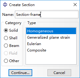
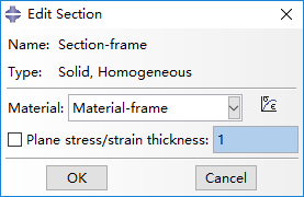
Create Sections
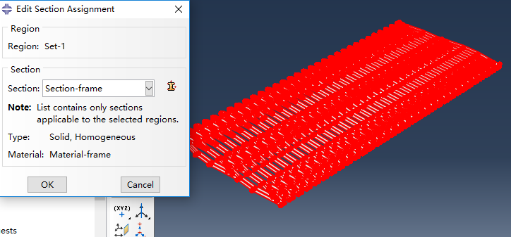
Double click on Sections in the model tree to create a new section. Set it to be a homogeneous solid and assign 'Material-frame' as its material.
|
|
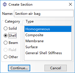
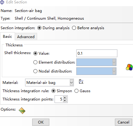
Create another section and set it to be a homogeneous shell and assign 'Material-air bag' as the material. Set the shell thickness as 0.1.
|
|
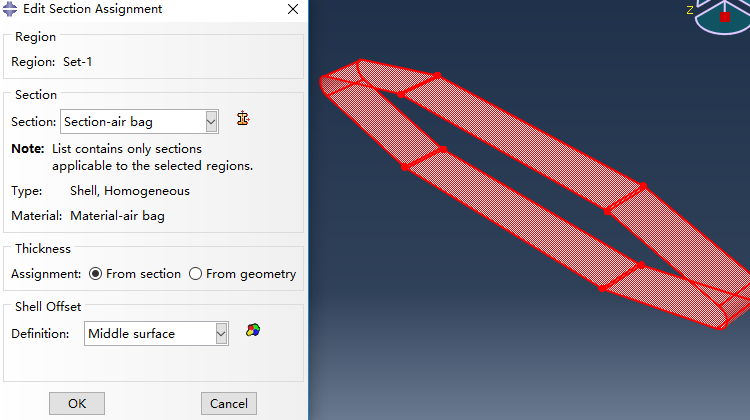
Edit Section Assignment
Last, assign the section property to corresponding part by selecting the entire part geometry.
Assemble
In this page, we first create instances from the imported parts for 'frame' and 'air bag', move the air bag towards proper position, and then replicate airbags in each chamber of the manipulator frame.
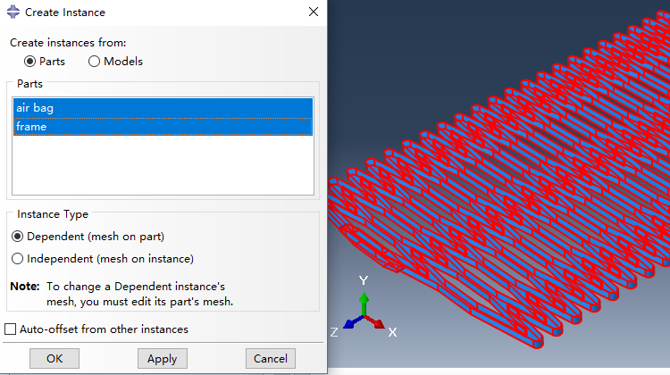
Create instance
Instances are created from imported Parts named 'frame' and 'air bag' in page 'Part', and we select instance type as Dependent (mesh on part).
Position air bag
Now the airbag has to be positioned properly. Firstly, the air bag is rotated 90 degrees around x-axis, forming a result posture shown as below.
Next, the air bag should be translated into a chamber of the manipulator frame, which is implemented based on a translation vector from the magenta point towards the orange point illustrated below.
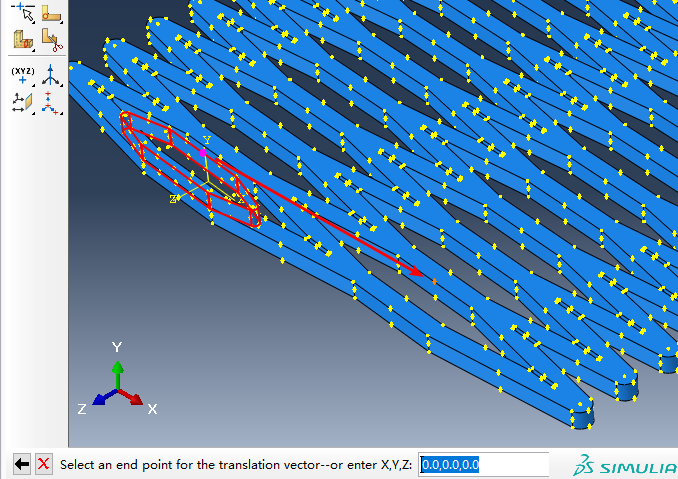
Then, we rotate the whole structure 90 degrees around y-axis, and the result is shown like this.
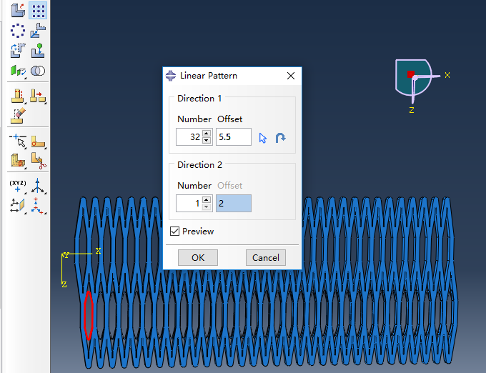
Linear pattern
Last, airbags are generated using Linear pattern, and set the Number as 32, Offset as 5.5 in Direction 1.
Create Steps
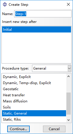
In this page, we create two steps, 'Step-1' and 'Step-2' for load simulations. 'Step-1' is created with procedure type of Static, General.
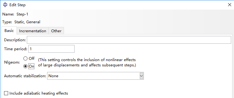
In the next window, turn on Nlgeom option in Basic panel.
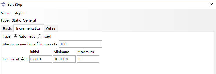
In Incrementation panel, we select type as Automatic, set Maximum number of increments as 100, and set Increment size as 0.0001, 1e-10 and 1 respectively for Initial, Minimum and Maximum.
|
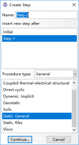
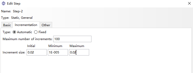
Next, 'Step-2' is created after 'Step-1', also with procedure type of Static, General.
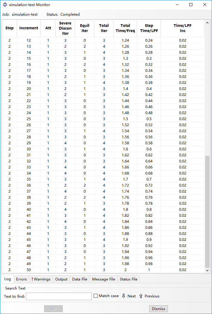
'Step-2' also needs enabled Nigeom in Basic panel. In Incrementation panel, we select type as Automatic, set Maximum number of increments as 100, and set Increment size as 0.02, 1e-5 and 0.02 respectively for Initial, Minimum and Maximum. Notice that the Maximum increment size of 0.02 here is set for convenience of the result analysis afterwards.
Add Contact Interaction
Create interaction property
First, we create the type of interaction we want to model. In the model tree, double click on Interaction Properties and create a new property of the type Contact, named 'Universal contact'.

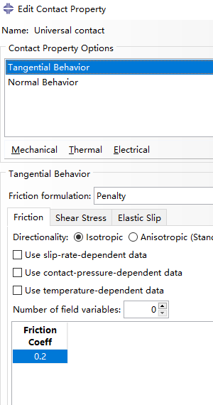
Add Mechanical > Tangential Behavior from the dropdown menu, and set friction coefficient as 0.2 (this parameter is of little importance).
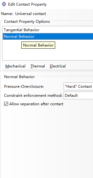
Next, add Mechanical >Normal Behavior as shown below.
Create interaction
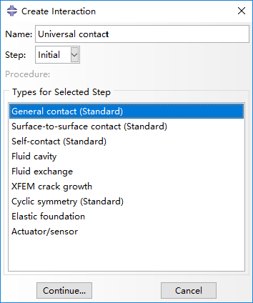
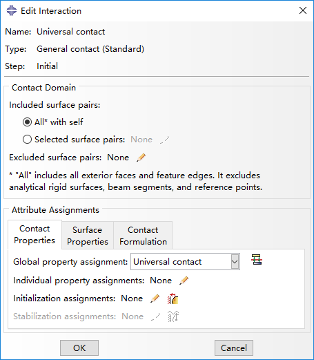
Then create an interaction named 'Universal contact', beginning from step 'Initial' with type of General contact (Standard).
Last, edit interaction by selecting All* with self for included surface pairs, Universal contact for global property assignment in Contact Properties panel.
Create Loads
Create sets and surfaces
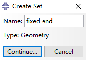
Firstly, we create a new set named 'fixed-end', by clicking 'Tools > Set > Create' button.
Continue and click on the faces (red) of the part that is going to be fixed.
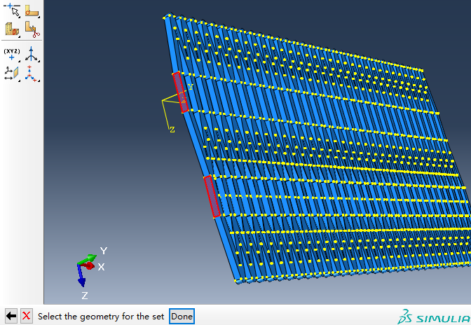
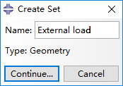
Repeat the operations above to create a new set called 'External load'.
Continue and select the two points (red) to be exerted force.
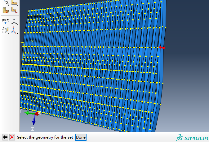
Then, we hide the frame using the button Remove Selected, only appearing airbags as the figure below.
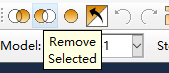
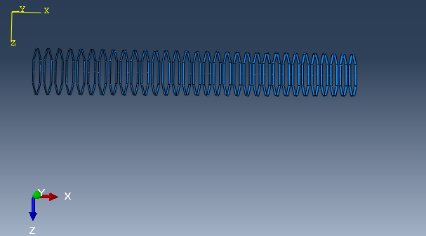
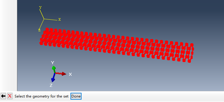
Next, we create another set named 'air bag' by clicking 'Tools > Set > Create' button again.
Continue and select all the airbags as a set that is going to be constrained afterwards.
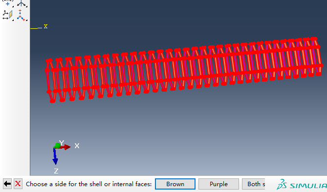
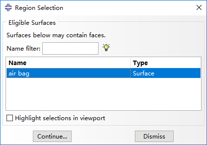
Then, create a surface also named 'air bag' by clicking 'Tools > Surface > Create' button.
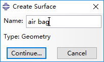
Click 'Brown' to select the internal face of these airbags.
Create loads
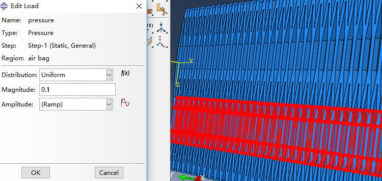
Under the 'Step-1', create a load named 'pressure' and activate Pressure as the selected type for the step.
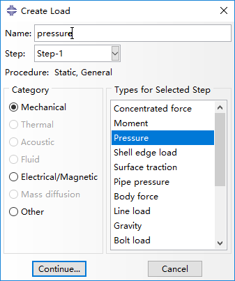
In the Region Selection window that appears, select the surface 'air bag' which we created earlier.
At the next window provide the pressure value to be applied in the airbags by setting Magnitude as 0.1 Mpa.
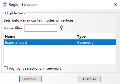
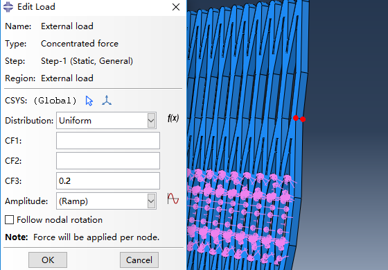
Next, we create a load of external force in 'Step-1' named 'External load' with type of Concentrated force.
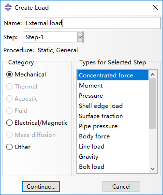
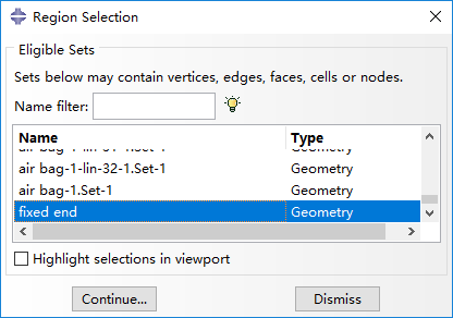
Select set 'External load' which we create earlier.
Continue and set CF3 as 0.2 N exerted on the two points (red) at the manipulator's tip.
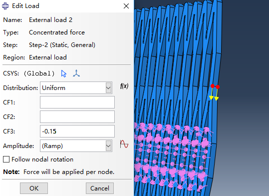
Then, create another external load named 'External load 2' in 'Step-2' with types of Concentrated force.
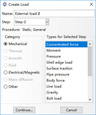
This load is implemented as a force in the opposite direction of the prior one, with a magnitude of 0.15 N (CF3 set as -0.15).
Set boundary conditions
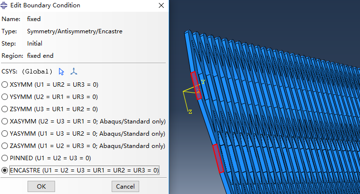
Create a new boundary condition named 'fixed' in step 'initial' and select Symmetry/Antisymmetry/Encastre.

In the next window select set 'fixed end'.
And select ENCASTRE to fix the red regions.
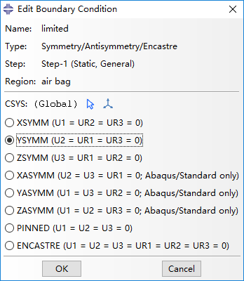
Next, create new boundary condition named 'limited' in 'Initial', with the same property as the prior.
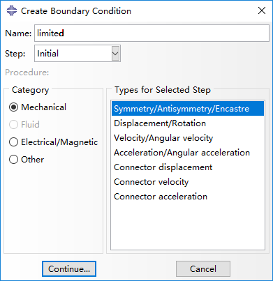
And select YSYMM to make airbags unable to move in y-axis.
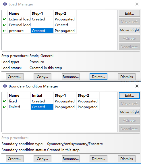
Finally, we can check the load, boundary information in Load Manager and Boundary Condition Manager.
Mesh
Seed edges
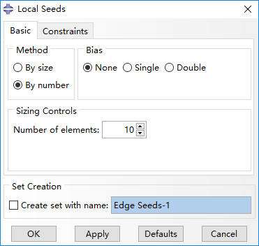
Firstly, select Part in upper right panel and choose 'frame'. Click Seed Edges (button with shaded background in the figure) and select all the edges.
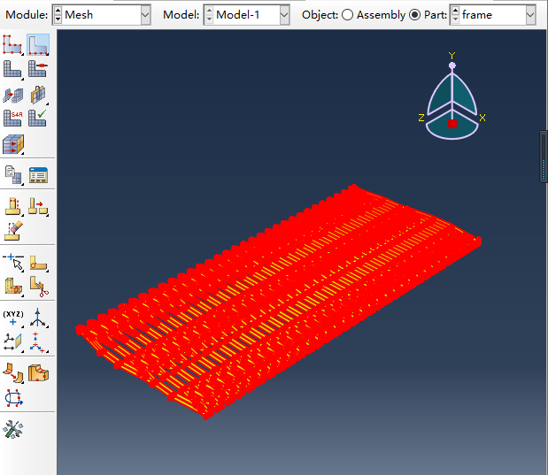
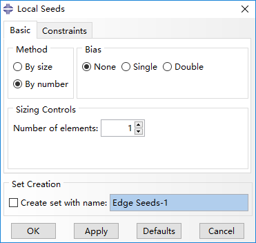
In the new window, we set the Number of elements as 10, which means each edge has 10 seeds.
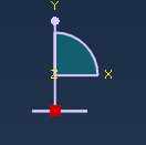
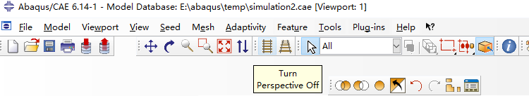
Then, convert the perspective by clicking at z-axis.
And click Turn Perspective Off.
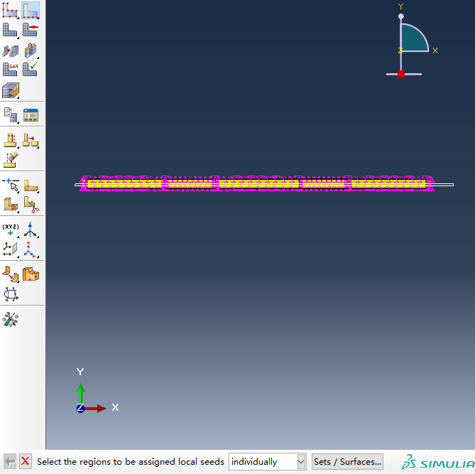
Because the slice is thin enough, we change the seeds on these edges along y-axis to 1.
Mesh
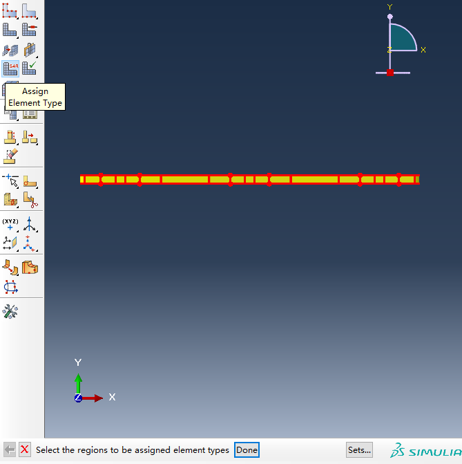
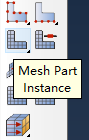
Next step, click Assign Element Type button.
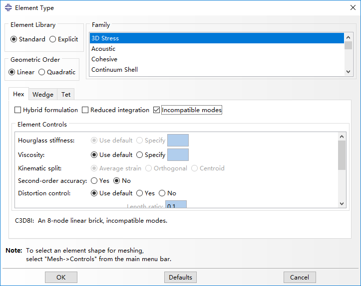
Enable Incompatible modes option, with other options set as default. Thus, the mesh type is C3D8I, as shown below.
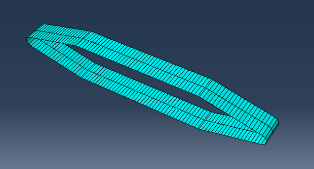
Then click Mesh Part Instance and get the meshed frame as shown below.

The mesh of airbag can be implemented in a similar way. The result is illustrated like this.
Run Job and Result Processing
Run job
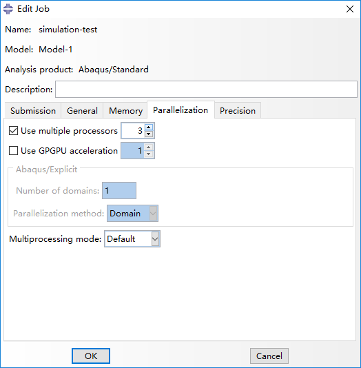
Firstly, we create a new job named 'simulation-test'.
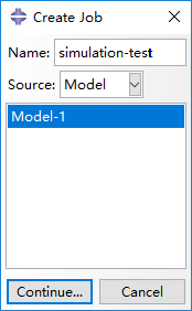
You can use the default settings, or change certain options (i.e. multiple processors) so that Abaqus can use more computation resources and complete the job faster.
Then Submit the job.
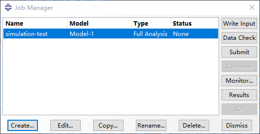
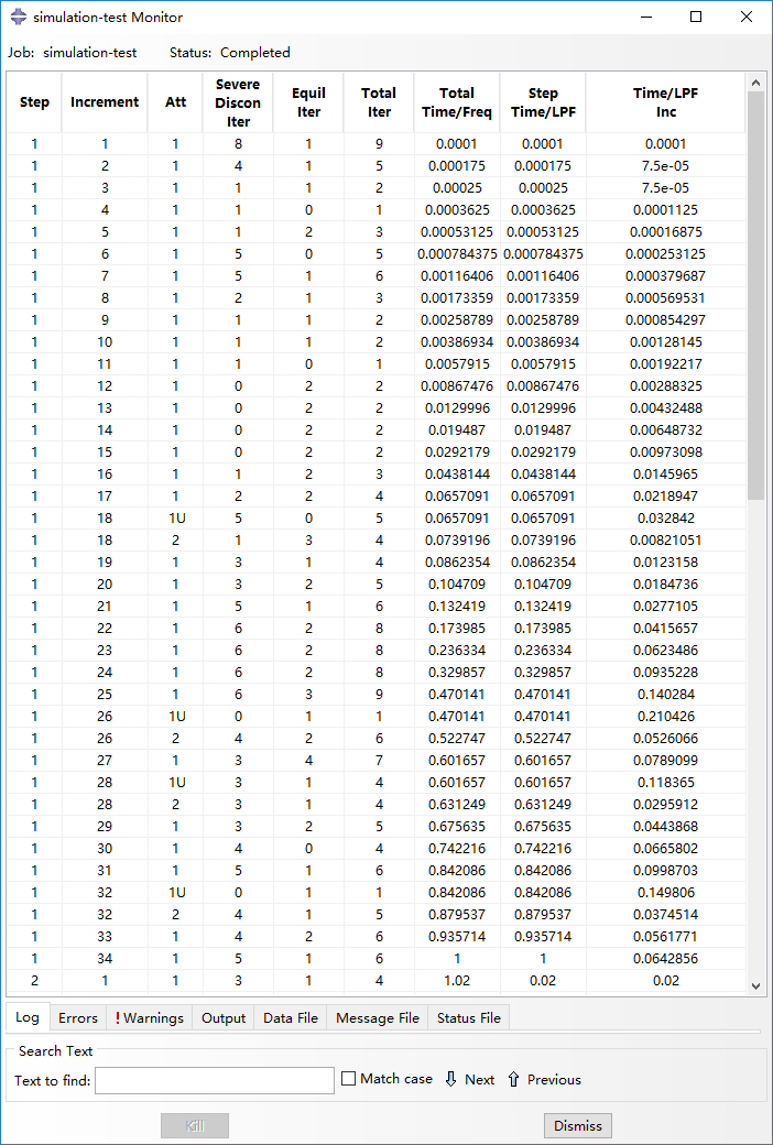
You can monitor the progress of the simulation by clicking on Monitor. A new window will pop up. In the Step Time/LPF column you can see the completed percentage of that step.
Result processing
Once the simulation finishes, you can observe and analyze the results by clicking on the Results. If you need to keep your results, they are saved in a large .odb file, typically in the TEMP folder or in the same directory as your model (.cae) file.
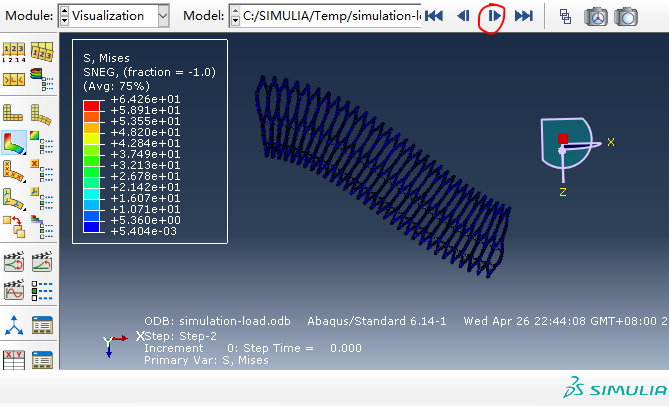
In Visualization module, the navigation arrows in the top right corner of the screen allow you to scroll through the step increments and see how the manipulator deforms. The figure below shows that the manipulator finish Step-1, and at the beginning of Step-2.
In homepage, we define the load capacity as the load moment when the manipulator's loaded end is on the same height with its fixed end, so we continue to click navigation arrows and use 'Tools > Query' to check the tip point's (red) displacement. As marked in red box, the tip point's displacement in the z-axis is -1.85mm when the time equals 0.52, which can be approximated that the tip has reached the same height with fixed end.
Thus, the load on the manipulator's tip can be calculated as (0.2 - 0.15*0.52)*2 = 0.244 N. Notice that the load is gradually exerted and proportional to step time. Besides, the force is exerted on two points, so it's multiplied by 2.

Then, use Distance to get the distance (248mm) between two selected points.
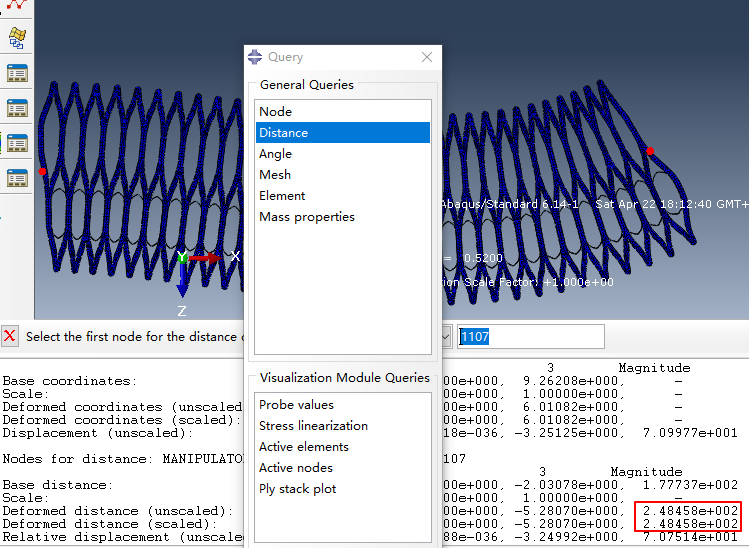
So, the moment is calculate as 0.244*0.248 = 0.0605 N/m. This value is calculated under a 2 mm thickness condition. For the real structure, the thickness is 60 mm, so the real moment is about 0.0605*60/2 = 1.82 N/m.
FEM for flexibility
In this section, we are mainly concerned with the impact of groove depth and wall thickness on the flexibility.
Cae here
Because all the operations have been introduced in the previous section, we will only show the difference.
The following is our Assembly.
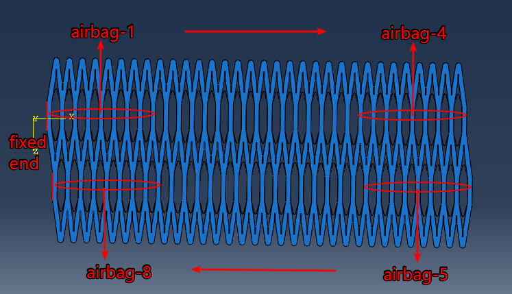
9 loads:
- Step-0: all airbag 0.001Mpa(The airbag establishes contact with the arm)
- Step-1: airbag-1 0.1Mpa
- Step-2: airbag-2 0.1Mpa
- Step-3: airbag-3 0.1Mpa
- Step-4: airbag-4 0.1Mpa
- Step-5: airbag-5 0.1Mpa
- Step-6: airbag-6 0.1Mpa
- Step-7: airbag-7 0.1Mpa
- Step-8: airbag-8 0.1Mpa
So, we can get the result like this.
We measured that area using Monte Carlo method. Furthermore, using L0, L1, R and D, the reachable space can be calculated by the formula. The calculated area approximately equals to the measured counterpart, which validates the calculation method.
(Advanced) Result Analysis
|
|
The variation of flexibility is illustrated in the figure above. We can find that as the groove depth grows, the flexibility increases, while as the wall thickness grows, the flexibility decreases. Both variations are monotonous.
As shown in the figure, the load bearing capacity increases monotonously as the wall thickness grows. However, the variation of load bearing capacity about the groove depth is not monotonous: it initially increases, and then decreases. We believe the cause is that as the groove depth increases, then the arm of gravity and load increases while the forces themselves decrease. Because the wall of a relatively large thickness confines the airbags’ inflation, the forces decrease slowly when the groove depth is relatively small. So their product initially increases.
Besides, the deformation of airbags is confined, so the increasing forces' of the arm is confined while the forces always decrease as the groove depth increases. So their product has an extreme value, and then decreases. Because of the non-monotonous variation, the load bearing capacity reaches an extreme value at a certain groove depth under every fixed wall thickness (white line in the right figure). On its left side, the flexibility and load bearing capacity both increase as the groove depth grows. Thus, values in this region are not concerning because both properties can be better on the right side of the white line.
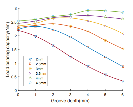
To get an explicit view of the load bearing capacity’s non-monotonous variation along with the groove depth, the performance of load bearing capacity under different fixed wall thickness are demonstrated in 2D plane in the figure below. From that, several conclusions can be drawn:
• As the wall thickness grows, the extreme point moves rightwards, so a deeper groove is required corresponding to a thicker wall for achieving maximum load bearing capacity.
• The curve corresponding to a 2mm wall thickness monotonously declines, with no extreme point. From the trend that the extreme point moves leftwards when wall thickness decreases, we can infer that when the wall thickness is less than a certain value, the extreme point has a minus groove depth. Therefore, an additional part at the intersection, instead of a groove, is required to realize a model with a thin wall.
• With a fixed groove depth, the load bearing capacity always increases as the wall thickness grows, but its rising range gradually reduces. So, it’s not effective to keep increasing the wall thickness when it’s already large. Instead, it is useful to increase the pressure.
Fabrication
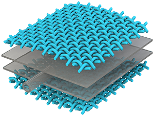
This section contains detailed step-by-step instructions for making a HPN manipulator. As explained in previous sections, the HPN manipulator consists of two parts: the main body consisting of 5 segments of honeycomb structure which were designed with different parameters, and pneumatic networks containing a mass of air chambers arranged regularly. The two parts are fabricated separately and then assembled together.
Process overview

|
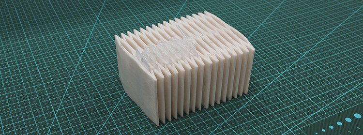
The fabrication method of the honeycomb structure was accomplised with the technology of 3D-printing, however, limited by the work space of 3D printer, the honeycomb structure of HPN manipulator was divided into 2 parts, each part was printed individually. The material we used to print is PolyFlex which is a kind of TPU that has good features of highly flexibility and a large strain-to-failure, is easy to be print by almost all desktop FDM/FFF printers. |

|
Pneumatic networks are fabricated manually. With the help of bag sealer machine, we can put Air Column Bag into pneumatic network. |

|
When finished with the fabrication of honeycomb structure and pneumatic networks, we can assemble them together easily. This is a single segment of HPN manipulator which consist of one segment of honeycomb structure and 4 pneumatic networks. When inflated with different pressure, the manipulator can deform in different directions as well as enlongate. |
Honeycomb Structure
As we discussed before, the whole manipulator consists five parts, in order to achieve a balance between flexibility and load bearing capacity, the frame of each part was designed with different parameters. This is a tutorial about the fabrication of a single segment.
Honeycomb structure was build with the technology of 3D-printing, The STL file for 3D-printing can be download here.
3D printer
MakerBot Replicator 2X Experimental 3D Printer
Cilck here to buy.

Material
PolyFlex (1.75 mm; 750g) White
Click here to buy.

Honeycomb structure

limited by the workspace of the 3D Printer, we divide the honeycomb structure into two sections and printed them independently. After that, we connected the two parts with clips. Here is an video shows the process.
|
|
Pneumatic Networks
This section contains detailed step-by-step instructions for making a pneumatic networks manually.
|
As explained in the design of pneumatic network section, the pneumatic network consists of 8 segments. The two adjacent segments are connected by a long silicone tube that is round. Further more, each segment has two airbag chambers which are connected by a short silicone tube. |

|
Process overview

|
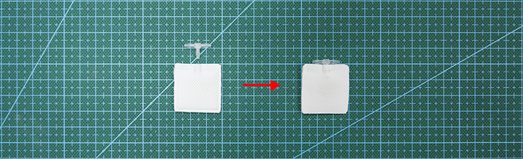
Prepare air bags The main body of pneumatic network is Air Column Bags whose material is PA/PE. The first setp to fabricate pneumatic network is cut a single column of air bag off.
|

|
Prepare silicone tubes Silicone tubes is used inside of pneumatic network to make it inflate fast. In this step, we cut silicone tube into 2 sizes.
|

|
Heat sealing Using the technology of heat sealing, we can divide a long air column bag into a series of air chambers. In this step, silicone tubes were put inside of channels when sealing.
|

|
Seal This is the last step to finish the fabrication of pneumatic network. In this step, a plastics straight through connector was sealed inside of the channels with hot glue. |
Bill of Materials
Airbag
Air Inflatable Rolls Bag
Click here to buy.

Connector
Value Plastics Straight Thru Connector , 400 Series Barbs, 1/16"ID Tube
Click here to buy.

Silicone Tube
uxcell 1mm x 2mm Silicone Translucent Tube Water Air Pump Hose Pipe
Click here to buy.

Syringes
Syringes
Click here to buy.

Scissors
Scissors
Click here to buy.

Knife
Utility knife
Click here to buy.

Tweezers
Tweezers
Click here to buy.

Clips
Binder clips
Click here to buy.

Ruler
Steel Ruler 1m
Click here to buy.

Hot Glue
Hot glue gun and hot glue
Click here to buy.

Sealer
Cellophane bag sealer
Click here to buy.

Step 1: Prepare Airbags
Cut off a line of PA-PE to make airbags between two sealing lines.


Mark the points to be heat sealed. The rules can be detailed in here.

After finishing all the marks, draw a solid line at the position to seal the whole airbag.

Cut at the point 5mm outside from that solid line.

Thus, we get a marked line to make airbags.

Silicone tubes inside

Firstly, get 8 silicone tubes, 4.5 mm each: directly cut off those bits at the length of 4.5 mm,

Similarly, prepare 7 tubes of 9.5 mm in the same way.


Step 2: Prepare Silicone Tubes
Silicone tubes inside
Firstly, get 8 silicone tubes, 4.5 mm each: directly cut off those bits at the length of 4.5 mm,
Similarly, prepare 7 tubes of 9.5 mm in the same way.
Step 3: Heat Sealing
This page illustrates the main step in fabricating the pneumatic networks. In this step, the design scheme is implemented by heat sealing the marked points on the airbag column in last step. Notice that the sealer should be configured with a proper heat-up time in one press to ensure the quality of airbags produced.

Firstly, put all the silicone tubes into the airbag column.

Inflate some air into the airbag column to ensure the tubes' free movements inside.

Temporarily seal up the airbag column by a clip.

Next, we begin the heat-sealing from the inside end.

Select a 4.5 mm tube and move it towards the end.

Fix the tube along one side of the airbag column, and heat-seal it at the red-dotted line shown in the figure below.

Seal it again at the other red-dotted line. The result is shown below.

Then, successively heat-seal the 9.5 mm tube at the four dotted lines in the figure below, and we finish a loop of airbag pairs. Then, the loop is repeated 6 times, and we seal another 4.5 mm tube at the opening end.

Now, we finish the heat sealing of the pneumatic network composed of 7 long tubes (9.5 mm) and 8 short tubes (4.5 mm). The heat-sealed airbag column can be separated into 16 chambers, and each two adjacent chambers divided by a short tube forms a pair of airbags. The two pairs in this airbag column are divided by a long tube, and each pair is to be put inside a chamber of the manipulator's frame. Thus, one airbag column containing 8 pairs in total can be just put into one line of a manipulator segment (each segment has four lines and need four airbag columns).

Step 4: Seal
In this page we will finish the last step of making pneumatic networks: sealing.
Prepare the following materials and tools: a heat-sealed airbag column, connectors, a tweezer, heat sealer and a hot glue gun.

Below is the unsealed pneumatic network.

Use heat sealer to seal the airbag along the two red dotted lines. Notice that this needs two sealing operations with a 5 mm gap at center for air inlet.

Fetch a connector using a tweezer.

Evenly smear the hot glue around a side of the connector. Notice that we need a quick finish or the glue will cool down and become undeformable and incohesive.

Insert the connector into the prepared air inlet, with the smeared side towards the inlet.

Press the connection area using fingers to ensure air tightness, and wait seconds for the glue to coagulate.

Thus, we have finished a column of pneumatic networks. It can be inflated using syringes and its air tightness can be examined by inflation under water.

Another Implementation of Air bags
In this paper, we use another implementation of air bags, as shown below.
|
Assemble
This section contains detailed instructions for assembling honeycomb structure and pneumatic networks together to finish the fabrication of HPN manipulator.
|
|
|
|
|
|
|
|

|
When assembling pneumatic networks with honeycomb structure, we can fold the pneumatic network from every short tortuous and plug it into every single chamber of honeycomb structure. The GIF below shows the process of assembly.

The GIF below shows the deformation of HPN manipulator when inflated.

Testing
This section firstly shows a complete manufacturing process of an HPN manipulator based on the design, modeling and simulation sections. Then, a protection test and performance measurement of flexibility and load bearing capacity are detailed for this HPN manipulator prototype. A few applications further validate this manipulator’s practicality. The purpose of presenting this testing process is to help readers determine appropriate methods to test the prototype’s performance, make comparisons with simulation results and guide the design.
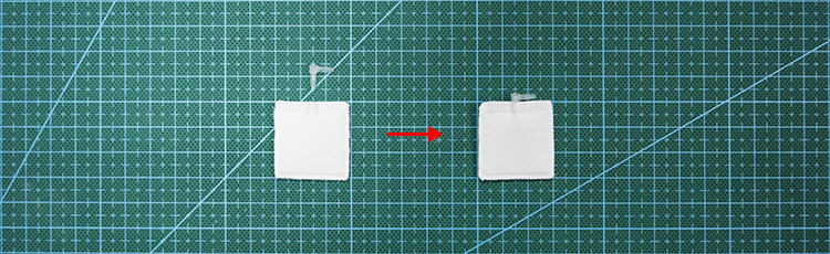
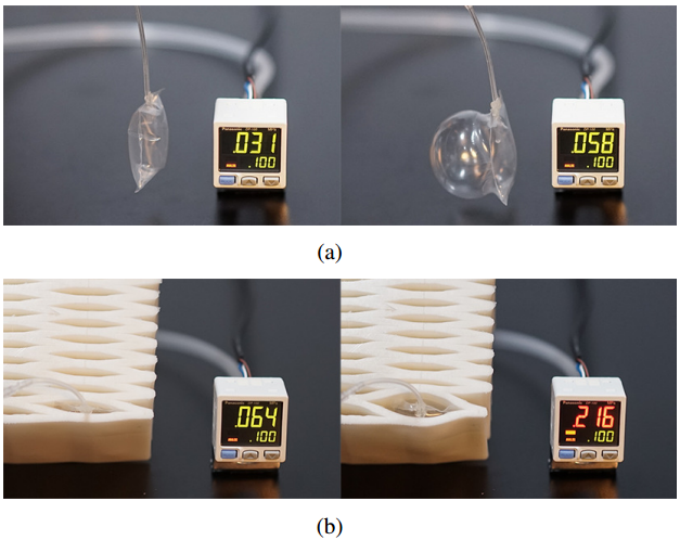
Protection test
The protection effect of the mainframe to the airbags is validated in this test. From the picture, it can be found that an airbag is fragile without protection: it makes irreversible deformation at a lower pressure (about 0.06Mpa); in contrast, it withstands a much higher pressure when surrounded by an HPN framework (about 0.216Mpa, 3 times of the former case).
A customized prototype
During the simulation section, we find how the manipulator’s flexibility and load bearing capacity vary with wall thickness and groove depth. For simplification, we do not select different wall thickness and groove depth for each single chamber, instead, we select 8 consecutive chambers as a segment, where the parameters remain the same. The whole manipulator is then constructed by 5 segments. As the segment becomes closer to the root ( horizontally fixed end), the load bearing capacity is expected to be stronger to hold the segments in front, so it needs thicker walls and shallower grooves.
The prototype is expected to have the load of 100 grams at an elongation of 50cm. The parameters selected for each segment are shown in the table aside, and it should be emphasized that the choices listed in the table are determined according to the importance sequence as: load bearing capacity > flexibility > wall thickness (the manipulator is expected to be lightweight so a thinner wall is preferred).
After determining the parameters, a prototype is fabricated, including a 3D-printed main framework with a kind of soft elastomer material (Polyflex), and airbags made of a kind of plastic membrane (Polyethylene/Polyamide, PE/PA).
| Mechanical Properties | 1-3 | 4 | 5 |
| Load moment (N·m) | 0.294 | 0.392 | 0.490 |
| Self moment (N·m) | 0.648 | 1.175 | 1.919 |
| Required moment (N·m) | 0.942 | 1.567 | 2.409 |
| Wall thickness (mm) | 2 | 2.5 | 3.5 |
| Groove depth (mm) | 3 | 4 | 4 |
| Selected moment (N·m) | 1.236 | 1.578 | 2.544 |
Flexibility test
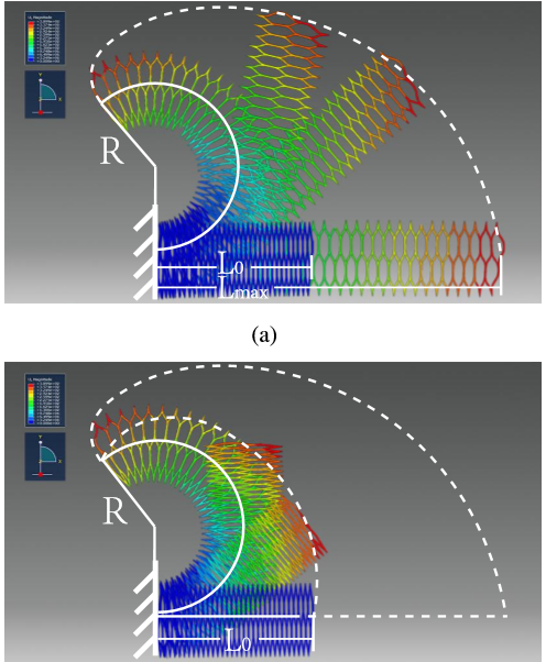
This figure shows a process of measuring this manipulator’s flexibility (as mentioned in the calculation part, we focus on the spatial reachable space). From the two snapshots, we can find there is a deviation between the manipulator’s deformation in simulation and prototype experiment. The main reason is that actual airbags have air tubes with thicknesses about 4.7mm, which enlarges the cavity height, thus the manipulator’s original length is lengthened and minimum bending radius is enlarged. And the elongation rate decreases because the maximum length isn’t affected. (The prototype is constructed with segments with different parameters which also changes the deformation shape, yet not the main reason.)
Further, a list of comparisons in flexibility between our HPN manipulator and OctArm VI [1][2] are shown in the table. The OctArm VI has a big advantage in length over the HPN manipulator, so it has a much larger reachable space and better flexibility. While the HPN manipulator is better in minimum bending radius and elongation rate, so its flexibility would be larger when their original lengths are the same.
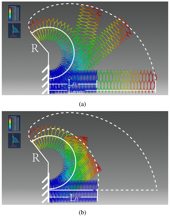
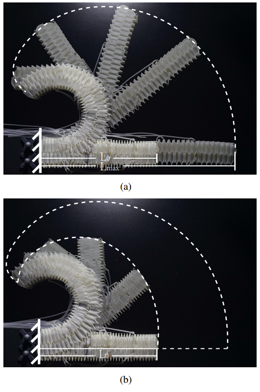
From the two figures above, we can see that both in simulation and prototype experiments, the manipulator’s reachable space is approximately measured by recording two boundaries and calculating the space between them. The manipulator is firstly straightly elongated from original length L0 to maximum length Lmax, and then deflated on the upper side from the fixed end to tip in order to bend upwards, leaving a record of outer boundary (white dotted line). When all the airbags on upper side are deflated, we record the manipulator’s minimum bending radius R. The inner boundary can also be recorded in a similar process, where the airbags on lower side are deflated from tip to fixed end (shorted white dotted line).
References:
[1]: Design and experimental testing of the octarm soft robot manipulator
[2]: Continuum robots and underactuated grasping
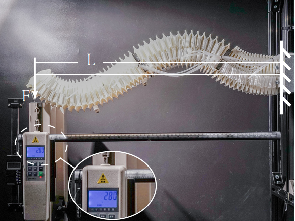
Load bearing capacity test
To increase the load bearing capacity, two supplemental segments are added as the root of the manipulator. For them, high load bearing capacity rather than flexibility is preferred. As shown in calculation section, the load moment increases as (k3−k1) increases, so the root segment is designed with asymmetrical grooves that only exist on the lower side. Therefore, the root part is capable of providing additional carrying capacity besides lifting the five segments above the horizontal line. Under the pressure of 90 Kpa, the manipulator exhibits a payload of 2.80N at a length of 63 cm. As mentioned in simulation, the manipulator exhibits a complicated shape instead of being straightly elongated under a load.
The manipulator withstands a heavier load in practical environments, because the manipulator usually winds to grasp or hold an object, which shortens the distance between the fixed end and the center of gravity of both the manipulator and the object, and thus lessens the load moment. In comparison with OctArm VI, the HPN manipulator has a less load moment. However, considering its load moment per unit pressure, HPN manipulator’s performance is better than OctArm VI (see the table below).
| OctArm VI | HPN Manipulator | |
| Length (m) | 1.127 | 0.630 |
| Load (N) | 8.89 | 2.8 |
| Load Moment (N·m) | 10.019 | 2.764 |
| Weight (kg) | 6.94 | 1.5 |
| Pressure (bar) | 5.51 | 0.9 |
| Load Moment / Pressure | 1.8183 | 1.96 |
Testing Manipulator’s Performance
The HPN manipulator’s performance shows great flexibility, load bearing capacity and ability to interface safely with humans. In the figure, (A) shows a process of grasping a ball by the HPN manipulator where it performs high compliance and flexibility; the manipulator exhibits high degrees of freedom as well as stability during movements in a fetching process in (B); (C) demonstrates a process of fetching a hammer and passing it to a man by the HPN manipulator, which shows proper load bearing capacity and cooperation ability.

Details: In (A), the manipulator first moves close to the ball, and then gradually bends to grasp it. After that, the manipulator bends to the opposite direction and place that ball on the top of a bottle. In (B), the manipulator first move a position where its tip can exactly hook the vial through a hole of only 1cm2. Then it stably moves towards the destination, adjusts the position elaborately and puts it down. In (C), the manipulator first bends downwards using its fourth segment, and then bends left to grasp a hammer, after that, it tightens and passed that hammer to a person by bending right using its root segment.
|
|
Downloads
| honeycomb_structure.rar | 238 KB | |
| pneumatic_network_dwg.rar | 42 KB | |
| abaqus_stp_files.rar | 202 KB | |
| simulation_flexibility_cae_file_0.rar | 13.96 MB | |
| honeycomb_stl.rar | 15 KB |