Fabrication
This section breaks down the necessary steps to mold and assemble the EGaIn sensor described previously. The sensor consists of two halves that are molded separately and then bonded together. The molding and bonding processes are assisted by an oven and spin-coater to speed up the curing and bonding procedures. EGaIn is then injected into the channels inside the sensor and electrical wires are attached. An overview of this process is given below.
| Overview of steps to be taken | |
|---|---|
(A) Velcro is laser cut into desired shape. (B) Velcro is placed in the bottom-half mold and encapsulated in stiff silicone rubber. (C) The encapsulated velcro in the bottom-half mold and the top-half mold are cast with soft silicone rubber. (D) After curing the bottom-half mold, a small amount of soft silicone rubber is spun on to it to act as an adhesive layer for lamination. (E) The top-half sensor is demolded and laminated to the bottom-half. (F) Liquid metal alloy is injected into the microchannels with one needle while a second is used to evacuate the entrapped air. (G) To complete the sensor, wires are inserted into the soft elastomer and encapsulated with rigid epoxy for strain-relief. | 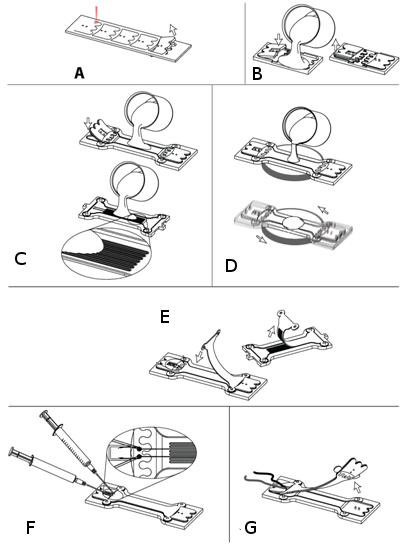
|
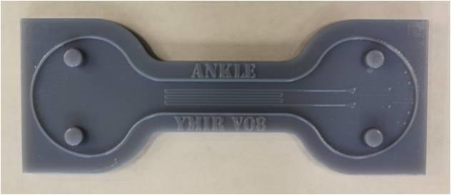
Diagram of full sensor

| Overview of Mold |
|---|

Top mold (mold, acryllic plate and transparency shown) |
Top mold: This half of the mold has the negative impression of channels that will contain EGaIn. Transparency and acryllic plate used to close the mold are shown in the bottom picture. |
| Bottom mold: | |
|---|---|
When molding the soft elastomer, use the transparency and the flat side of the top plate. When molding the stiff elastomer, use the raised side of the acrylic plate. | 
Bottom mold (mold, top plate and transparency shown) |