Modeling
When designing multi-segment compliant fingers with shape deposition manufacturing, deterministic tools should be sought to ensure that relevant design criteria are met (for example, finger stroke or transmission ratio). Finite element simulations can be employed for this task. However, the behavior can also adequately be described using first principles and beam theory.
Please read this document for a detailed description and derivation of the analytical model.
An illustration of an tendon-driven finger with a single compliant joint is shown in Figure 1. The finger consists of a rigid section (subscript s) and a flexible section (subscript f). Material properties alternate from low-modulus (Ef) joints and high-modulus (Es) segments. The finger is actuated by a tension force T which establishes a moment about the distal-most compliant joint.
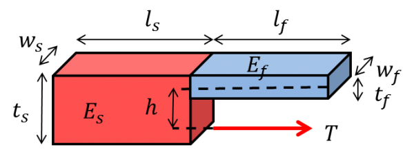
The simplified model assumes that the deformation behavior is dominated by an applied moment M=Th at the distal segment of the finger and contributions from gravity and reaction forces in the x-direction are negligible. We can use superposition to determine the overall deflection at the distal end of the finger by propagating internal moments back to the proximal end and defining a global displacement with respect to the origin of the proximal-most segment (the global origin).
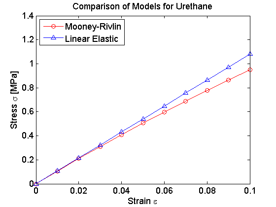
The exact behavior of the low-mod flexible joint is difficult to model analytically. Typically, rubber elastomers are modeled by the Mooney-Rivlin hyperelastic model, which contains coefficients that must be empirically determined. An example curve comparing a Mooney-Rivlin fit to a linear elastic approximation for urethane is shown below; observe a ~15% error between models at 10% strain.
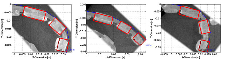
A linear approximation to the stress/strain behavior is suitable for qualitatively evaluating different configurations for relative performance. An example of such an analysis is shown below, where three different finger configurations were compared both analytically and empirically. In the left-most finger, the joint stiffnesses are proportionally decreasing from proximal to distal, resulting in a large deflection of the distal-most joint. The middle image shows a finger where each joint stiffness is identical, and it behaves more like a cantilever beam. Finally, the right-most image shows a configuration where the middle joint is the weakest.
A rigorous derivation of an approximate model, as well as MATLAB source code, is in the attached .pdf. The attached zip file contains the MATLAB files.
Bibliography
Odhner et al. (in press) “A compliant, underactuated hand for robust manipulation”
Gafford et al. (2014) “Shape Deposition Manufacturing of a Soft, Atraumatic, Deployable Surgical Grasper”
Dollar and Howe (2010) “The highly adaptive SDM hand: Design and performance evaluation”
Dollar and Howe (2006) “A robust compliant grasper via shape deposition manufacturing”
Binnard and Cutkosky (2000) “Design by Composition for Layered Manufacturing”
Contributors
Joshua Gafford