Fabrication of cast acrylic parts
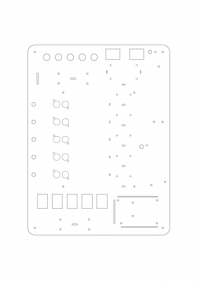
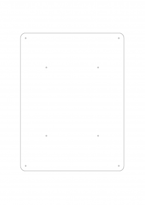
300mm x 400mm x 4mm cast acrylic sheet has been used for top and base plate for the control board. Following figures shows the AutoCAD drawing of both top and base plates and this AutoCAD drawing was used to laser cutting process.
Main parts of the control board
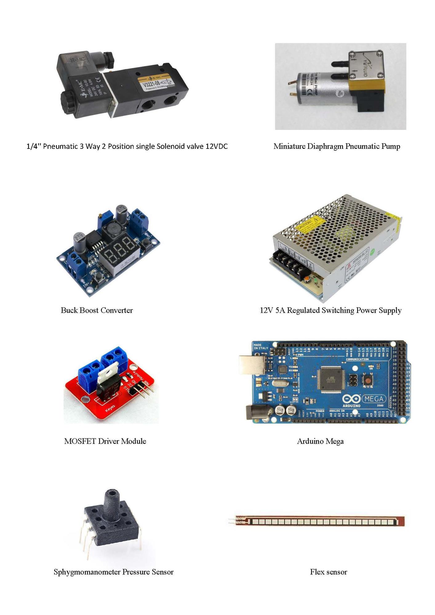
The below figures show the main parts which were used to develop the pneumatic control board.
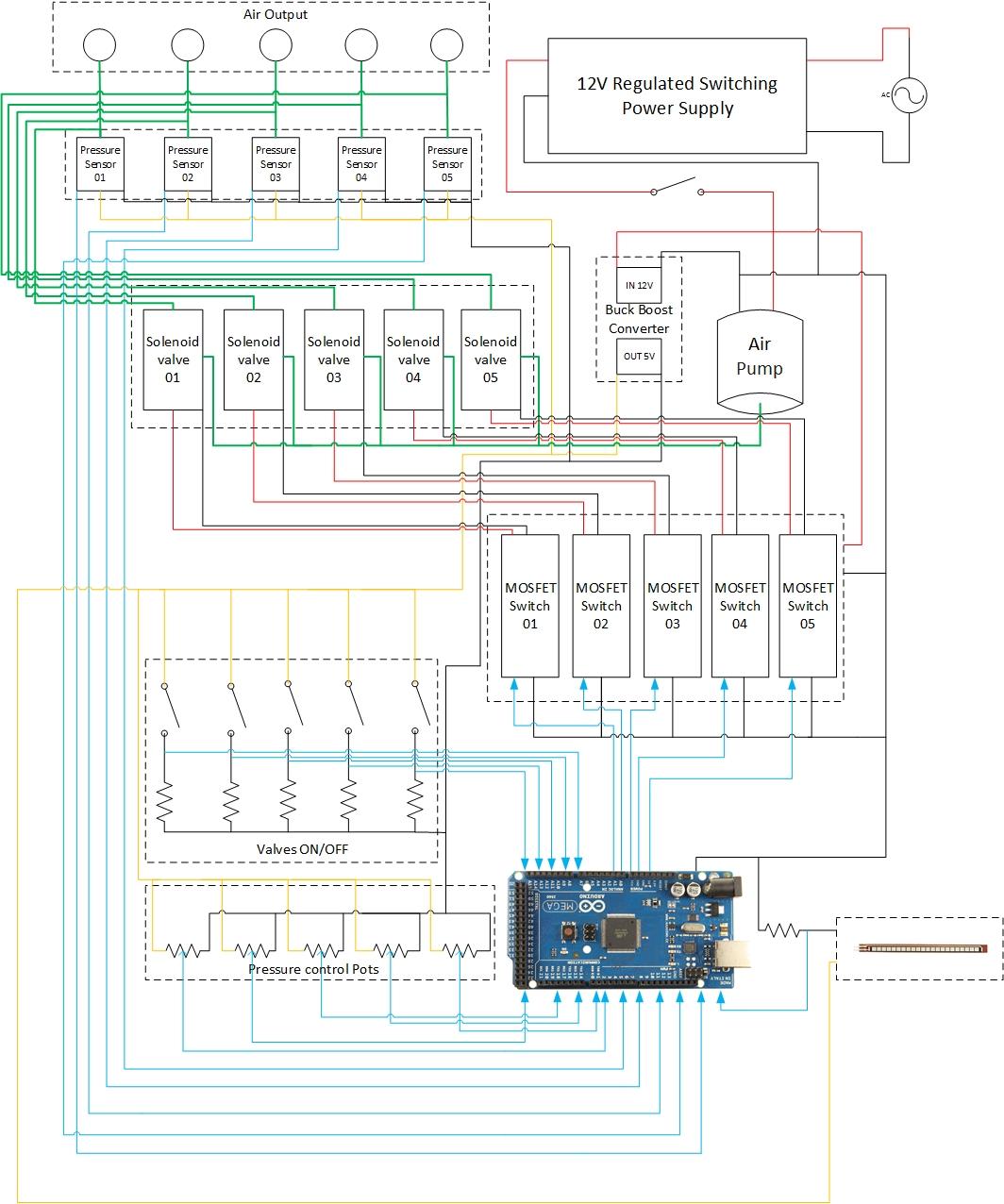
 Wiring diagram of control board
Wiring specifications of the control board
Wiring Colour | Type of signal |
Red | 12vdc |
Orange | 5vdc |
Black | 0vdc |
Blue | 0-5vdc (logic) |
Green | Pneumatic |
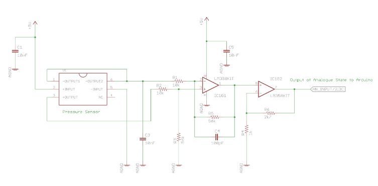
Circuit diagram of pressure sensor and differential amplifier
Following figure shows circuit diagram of Sphygmomanometer pressure sensor and differential amplifier’s connections. Pressure sensor has the capability of measuring a range of pressure values. It was driven by 5 VDC and 0-25 mV was the output signal. Therefore a differential amplifier circuit was used to amplify 0-25mV up to 200 mV to 3.5 VDC swing because the strength of the output signal was not sufficient to interface it with an Aruduino.
