After all the actuators have been fabricated, the next step is to assemble the robot.
Step-by-step procedure:
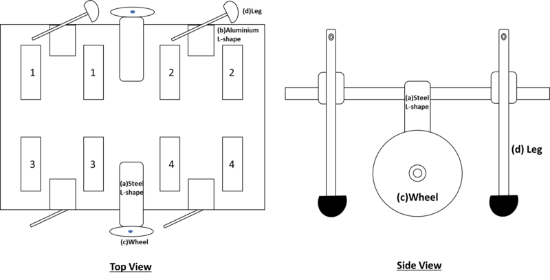
1. Screw and assemble all the components, aside from the diaphragm actuator devices, onto the large acrylic board with customised grooves (e.g. steel and aluminium L-shaped connectors, wheels and legs) as shown in Figure 19.

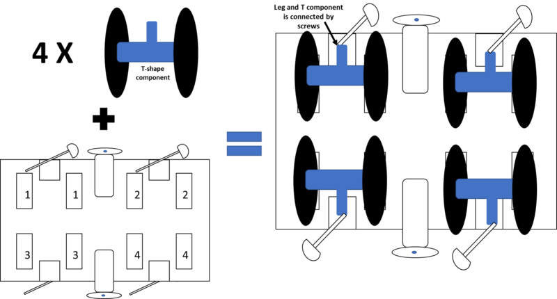
2. After the legs and wheels have been attached to the acrylic board, position the diaphragm actuators on their designated spots in the grooves in the acrylic board (refer to Figure 20). There should be 4 pairs of diaphragm actuators; each pair has a T-shaped component in between the centres of the inner sides of the circular films, and each pair has a C-shaped component holding the two acrylic rings of the diaphragm actuators together to balance the high tension in the stretched out elastomer films.

Figure 20: Installation of actuators onto supporting structure
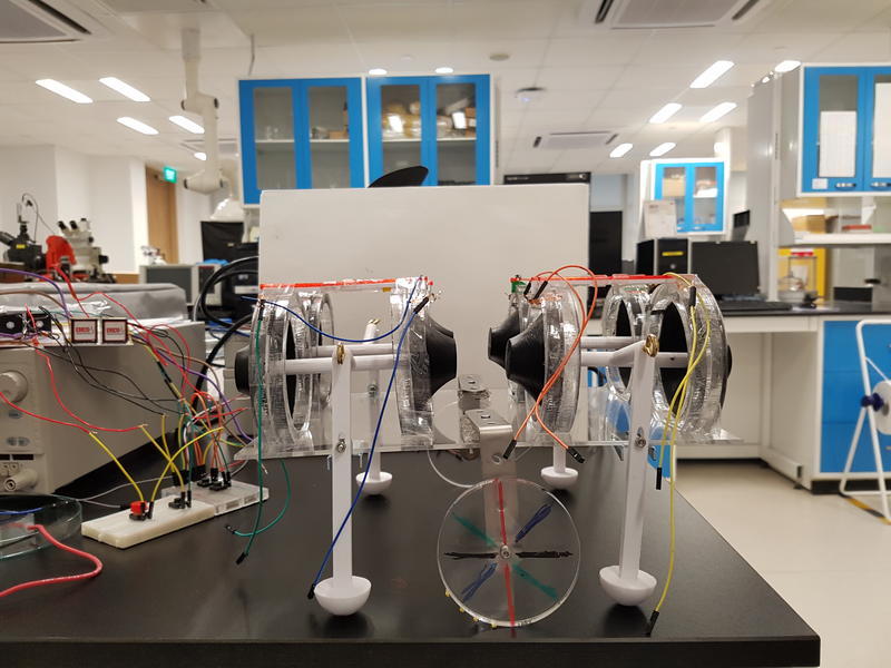
3. Attach the copper tapes sticking out of the diaphragm actuators to wires leading to the electrical supply. Be careful to ensure that opposite polarity of the electrodes on opposite sides of the same film. Each actuator should be able to be activated independently of the others.

Figure 21: Completed robot
