Hardware
Electronic Components
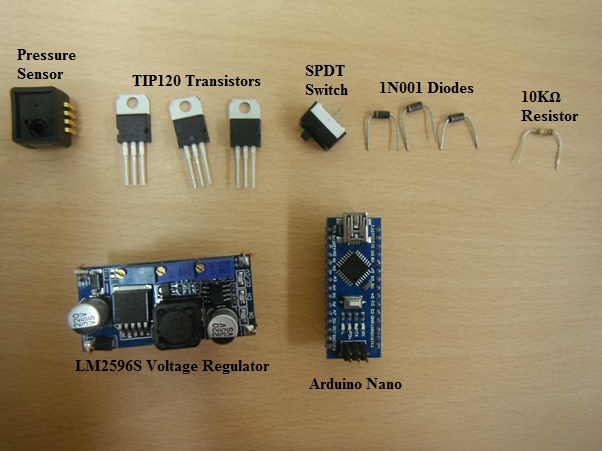
Actuation Components
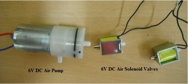
The solenoid valve has a metal side and plastic side. The metal side should be connected with the high pressure side to prevent excess leakage. The valve has two wires, with as no polarity. You can extend the wire by soldering longer wires to it. Also you can use different colours of wires to be able to distinguish between the two wires.
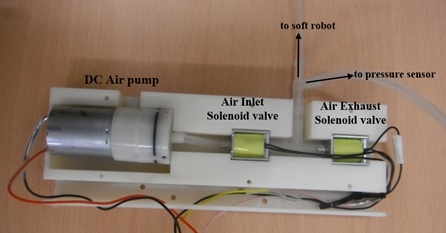
The pump and solenoid valves are arranged as shown in the image below. Two solenoid valves are required to carry out inflation and deflation cycles. One solenoid valves act as the inlet valve through which air always enters the soft robot. The second solenoid valve acts as the exhaust valve that expels air from the system when open. Both solenoid valves are arranged in series as shown.
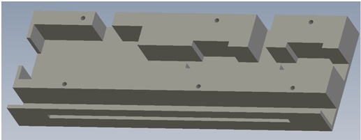
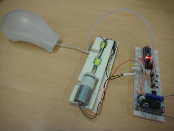
In order to facilitate compactness of the system, all the actuation components are placed inside a 3D printed casing. This casing was designed in SolidWorks and printed with ABS plastic using a HP DesignJet® 3D Printer. An image of the casing is shown below.
download custom 3D printed casing
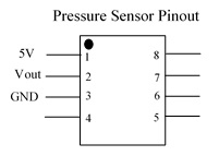
Pressure Sensor
The pin out of the pressure sensor and its connection is indicated below:
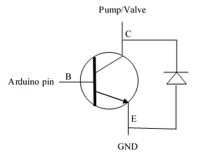
Transistor Connection
Each of the transistors are connected to the pump as shown in the diagram below. A complete schematic is found on the schematic layout page
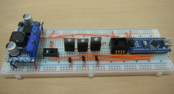
The components are now connected on a breadboard as indicated in the schematic layout. The connection of the electronics components on a breadboard is shown below.
The completed arrangement of the circuit is shown below
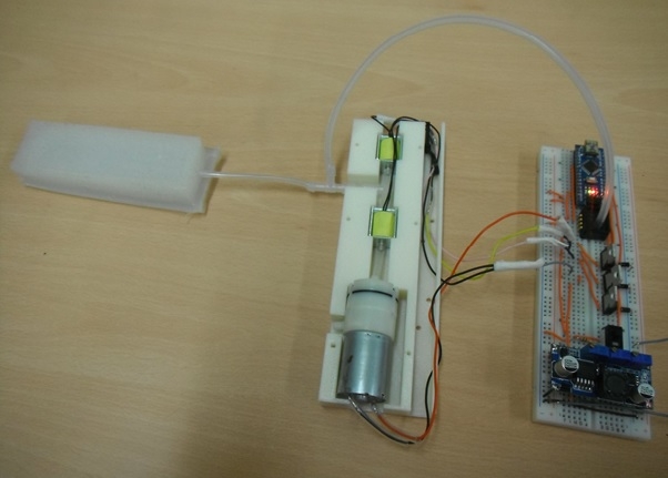
The circuit in operation is shown below
Contributors
Victoria Oguntosin