Electronics Fabrication
Modifications to the Fluidic Control Board
Follow the steps for creating the basic Fluidic Control Board on the Soft Robotics Toolkit Page.
The modifications we made to the fluidic control board are represented in this fluid control board schematic. You can use this reference when creating your own control board. Each voltage and data signal wire is color-coded to prevent confusion. Remember to be careful when working with electronics! The low voltages used in this project are still enough to do some harm.
Adding the Pressure Regulators
Instead of connecting the pneumatic tubing from the solenoids directly to the actuator outputs, route the pressure regulators in between. Each regulator requires 5 volts and a PWM data transfer signal to operate. First plug in the ground wire. Then plug in the voltage wire into the 5V source. Finally, plug in the data transfer wires into the PWM ports on your Arduino.

Figure 47: The pressure regulator integrated into the fluidic control board
Adding the LCD Debugging Screen
The LCD Screen requires 5 volts and 8 PWM data transfer ports to operate. First plug in the ground wire. Then plug in the voltage wire into the 5V source. Finally, connect 8 wires from the Arduino into the data ports of the LCD.

Figure 48: The LCD Debugging Screen integrated into the fluidic control board
Sensor Glove
Creating the Pressure Sensing Glove is a simple process requiring only a few key steps.
First, solder a wire onto each pin of the sensor.
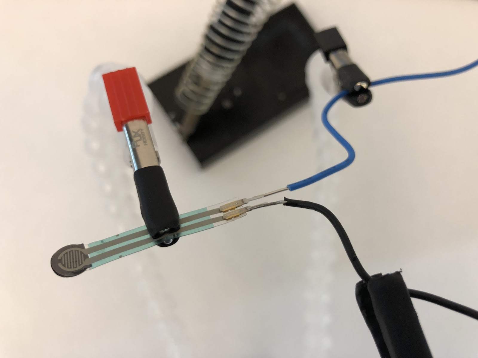
Figure 49: Using the Helping Hands to solder wires to the force sensor
Next, place the sensor on the finger of the glove where the pressure will be applied.
Originally, we had put the sensor on the inside of the glove, believing that the glove would protect it from clay debris. However, we soon realized that because the glove would be protected by an additional nitrile glove, it would be unnecessary to put the sensor on the inside of the glove. Thus, we decided that it would be better to attach the sensor on the outside of the inner-glove for easier access. Special thanks to Mrs. Jacob for helping us sew the glove!
Then, use electrical tape to create a pad on the tip of the finger where the face of the sensor will sit.
Finally, sew the sensor and wires along the length of the finger and down to the bottom of the glove. Once the glove is turned back inside out, it is ready to use! Plug it into the voltage monitor port of your Arduino to start reading values.


Figures 50 and 51: The completed sensor glove freshly sewn and the glove turned inside out
