Step 4: Equipment Setup
The equipment setup provided here serves only as a guideline. The only requirement is the ability to measure pressure in the line and measure the resistance (or voltage) between the leads of the sensor. A high level overview is presented below.
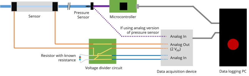
Measuring Pressure
If the digital (I2C) version of the pressure sensor is being used, connect the SDA, SCL, VCC, and GND pins to the respective pins on the microcontroller. This guide will not provide detailed instructions for communicating using I2C, please consult the datasheet for the specific microcontroller.
If the analog version of the pressure sensor is being used, connect the 0-5V or 0-3.3V output from the sensor to the analog input of the microcontroller or data acquisition hardware.
Measuring Resistance
Data acquisition device setup:
- Analog out: 2 Vpp sine wave (+ - 1V) at 100Hz
- Analog in: RSE mode (Single-Ended-Grounded Reference) with voltage divider circuit as explained in the Measuring Resistance with AC page
Choosing the Resistor
To get the most dynamic range out of the sensor, the resistance of the resistor in the voltage divider should closely match the sensor's resistance at rest.
Choosing the resistor is done by following process:
- Choose an arbitrary resistance, a good starting point is 80 kOhms.
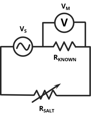
- Measure the response of the sensor at rest. Let's say we get a \(V_M\) of 0.2 volts.
- Calculate the resistance of the saline water with \(R_{SALT}=\frac{R_{KNOWN} \times V_{M_{RMS}} }{V_{S_{RMS}}-V_{M_{RMS}}}\)
- Select a resistor with a resistance close to \(R_{SALT}\). If the voltage at rest is not near 0.5 volts, reiterate by repeating steps 1 to 3.
Bibliography
Preechayasomboon et. al. Multi-Modal Sensing and Actuation in Biomechanical Hydraulic and Pneumatic Systems.
Contributors
Pornthep Preechayasomboon
Gaurav Mukherjee
Eric Rombokas