Additional Parts
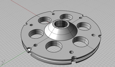
Each tendon is attached to a servomotor. More specifically, to a pulley that is connected to the shaft of each servomotor. This is why six supports of servomotors and six pulleys were designed and built.
The servomotors used are rated to a 0° to 180° span, although in practice, each one turns in the range of 35° and 158°. That means we need to use a pulley that could give us enough force to pull the different parts of the manipulator, while keeping an appropriate stroke according to the simulation's results. Each section of the manipulator was measured to an elongation of 1.5cm, twice this distance must be considered for the second section. Therefore, a pulley of 3.6cm of diameter was designed , giving a safe 3.8 cm of stroke.
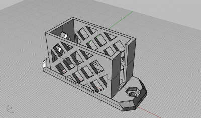
To keep the servomotors in place, a support visible on the picture below had to be designed. This design allows the six actuators to work in a reduced volume, while keeping the cables free from tangling up and leaving at the same time enough room for the pneumatics tubing.
Bibliography
Robinson et al. (1999) Continuum robots-a state of the art
Walker et al. (2013) Continuous backbone “continuum” robot manipulators
McMahan et al. (2005) Design and implementation of a multi-section continuum robot: Air-Octor
Neppalli et al. (2007) Design, construction, and analysis of a continuum robot
Bosman et al. (2015) Domain decomposition approach for FEM quasistatic modeling and control of Continuum Robots with rigid vertebras
Duriez, et al. (2008) Contact skinning
Duriez et al. (2013) Control of elastic soft robots based on real-time finite element method
Contributors
Thor Bieze
Frédérick Largillière
Sandra Hage Chehade
Mario Sanz Lopez
Christian Duriez