
Fabrication: A step-by-step guide (part 1)
This section presents all the steps needed to build the prototype. Some comments regarding possible problems or improvements in the process were added. These steps are:
- Fabrication of pneumatic actuators
- Printing the rigid platforms
- Building one section of the robot
- Building the base frame
- Final assembly
Fabrication of the pneumatic actuators
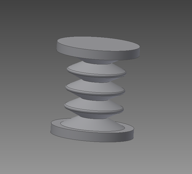
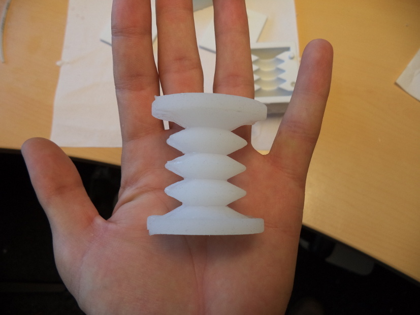
The soft backbone of the manipulator is composed of pneumatic actuators. These actuators are made of silicone rubber, and when inflated, they elongate longitudinally.
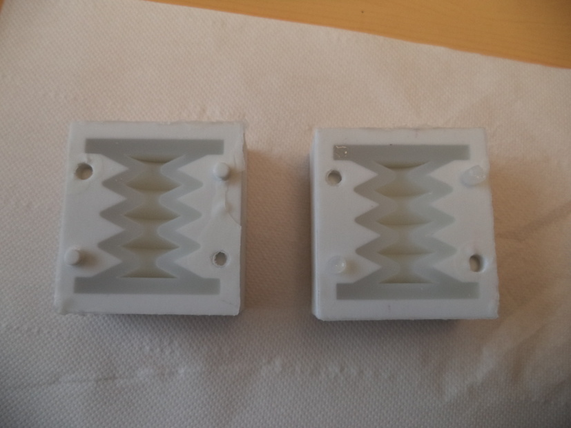
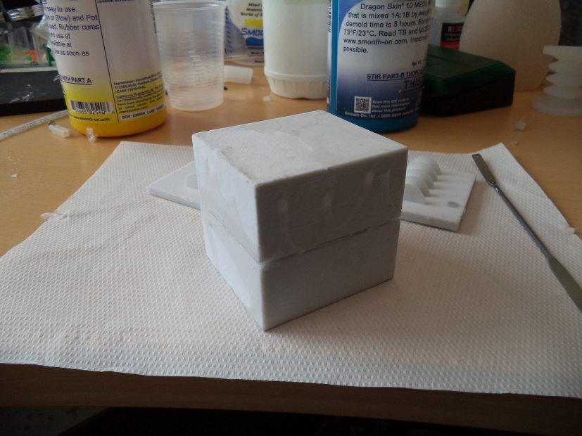
The first step to casting the actuators is printing the mold. The molds were designed to hold half of the actuator. In this case, the molds were made out of plaster using the ProJet 460 Plus printer, but molds made of a conventional plastic for 3D printing should do just fine as long as its surface is conveniently lubricated. This choice was motivated by the smoother surfaces produced by the plaster post-treatment with cyanoacrylate, making the unmolding much easier.
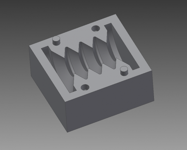
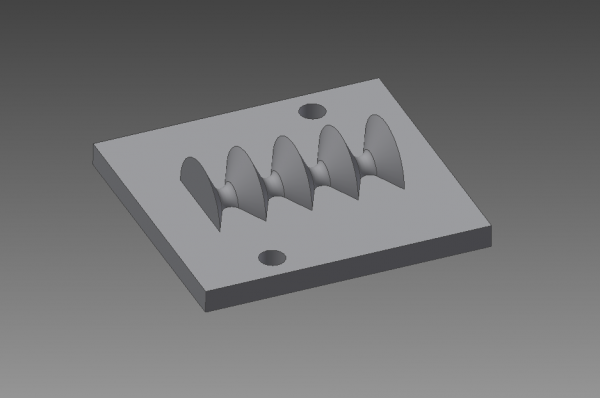
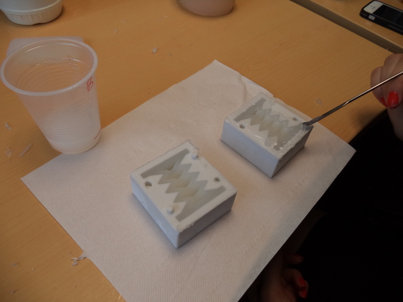
Once the molds are printed, it is time to cast the actuators. For this, Dragon Skin 10A silicone rubber is used. This silicone comes in a two-compound presentation which is really easy to prepare: just mix part A and part B in a 1:1 ratio, according to the amount of silicone you will need. If you have access to a vacuum chamber, you can put the silicone mixture in it to take out all the bubbles that can appear when the two parts are mixed. This allows to have a really homogeneous silicone piece.
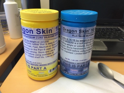
Once the silicone mixture is ready, simply pour some mixture into the molds until the mold cavity is completely full. Then, put the cap on the mold while being careful with the alignment between the mold and the cap. For this initial test, we casted just two halves to have one actuator.
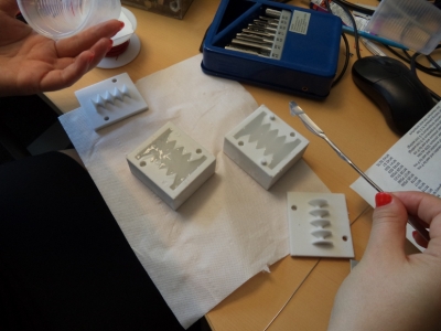
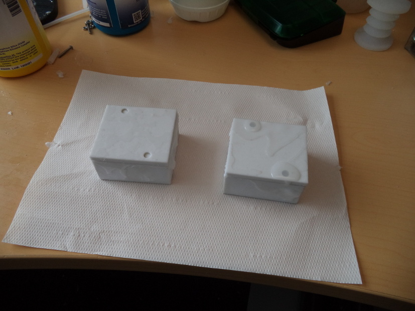
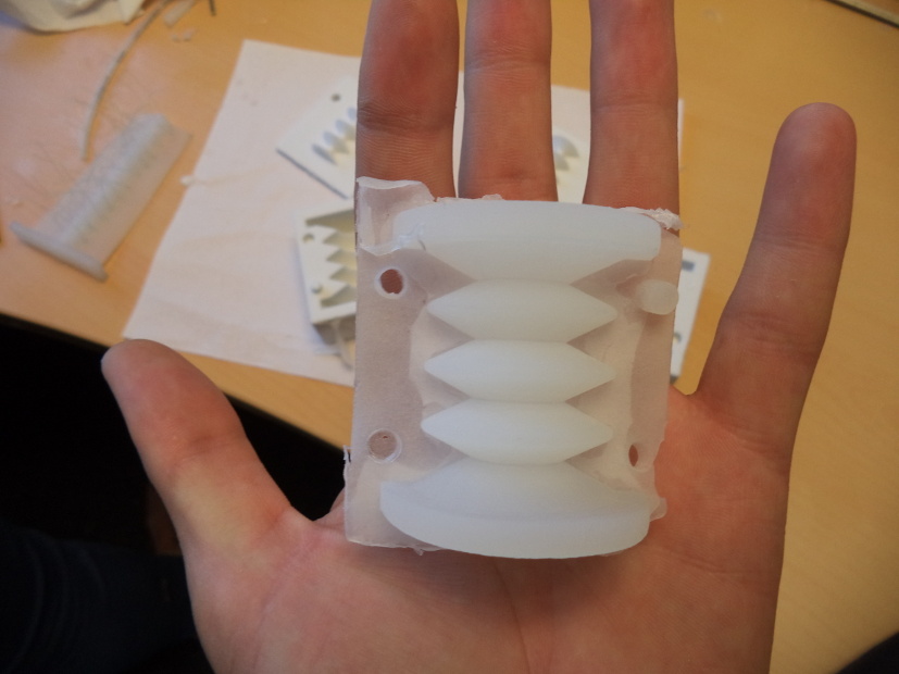
The two halves of the actuator should cure after about 3 to 4 hours. To join them, put some silicone on the edge of the wall of the piece and use the molds to align each half. Once the silicone is cured, you can take out the actuator from the molds. Use a hobby knife to remove any excess of silicone from the actuator.
The rigid platforms
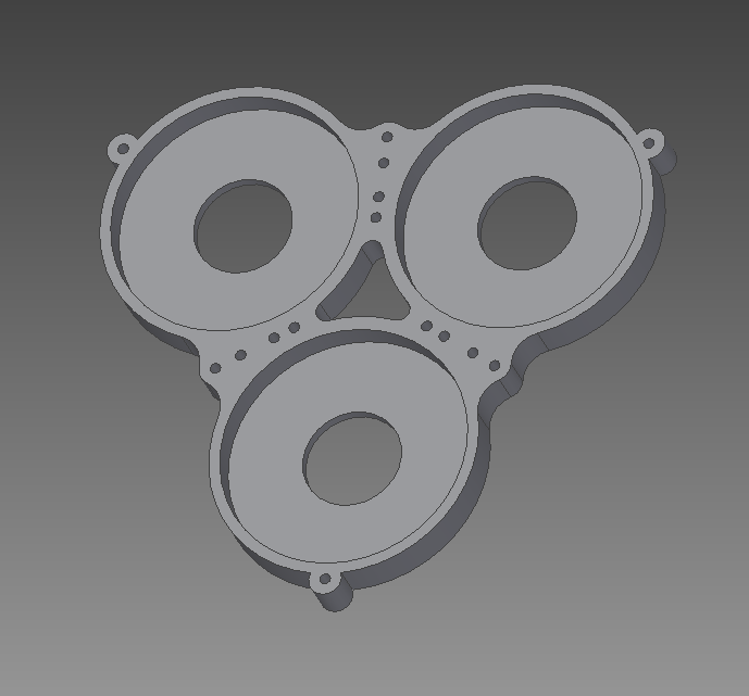
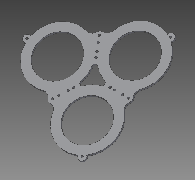
There are three different types of rigid platforms involved in the assembly of the manipulator. These platforms have sockets that allow us to keep the actuators in place. The sockets have an entry hole for the polyethylene tubes. All of these platforms use a second piece on top that functions as a cap, this cap makes it easier to put the actuators on the sockets.
The first platform is the base, which is attached to the wooden plank and receive the first three pneumatic actuators. To attach this platform to the plank, Ø4mm bolts were used, long enough so that nuts can be fastened to the other side of the plank. Another three Ø2.5mm 10mm long bolts are used in the center part of the platform to fix the cap in place. Six more holes between the sockets are used to guide the cables along the manipulator.
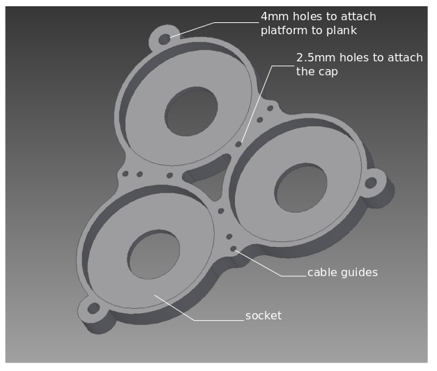
The cap is placed on top of the platform and is fixed to it using bolts.
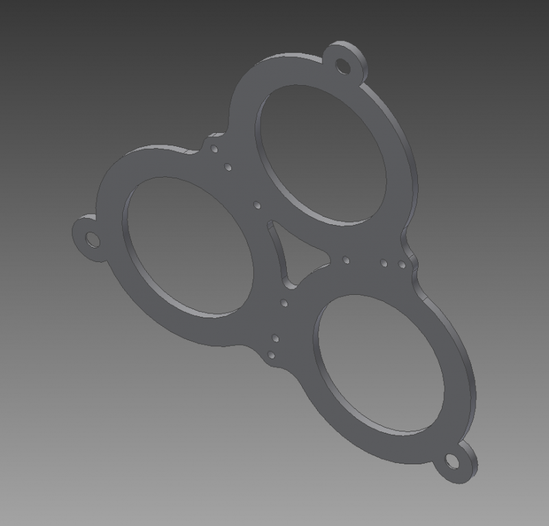
The middle platform is based on the same design. This platform connects the first section to the second and is composed of four pieces because it has six sockets in total and 2 caps. There are no 4mm holes and the bolts used to assembly these part are longer (30mm). A slight modification is done to the upper socket part in order to allow the connection of the tubes that supply pressure to the second section. Both cap pieces used in this platform are exactly the same.
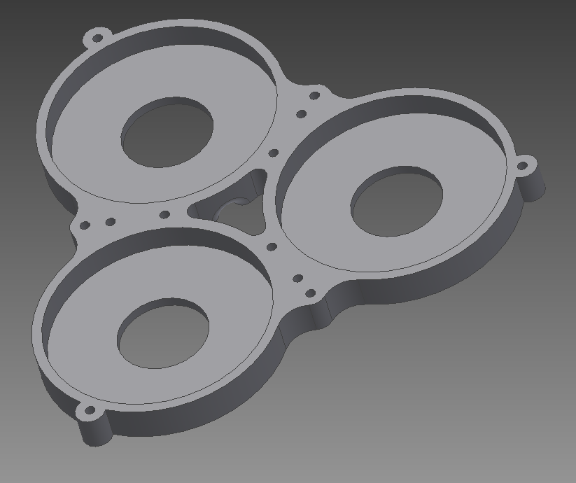
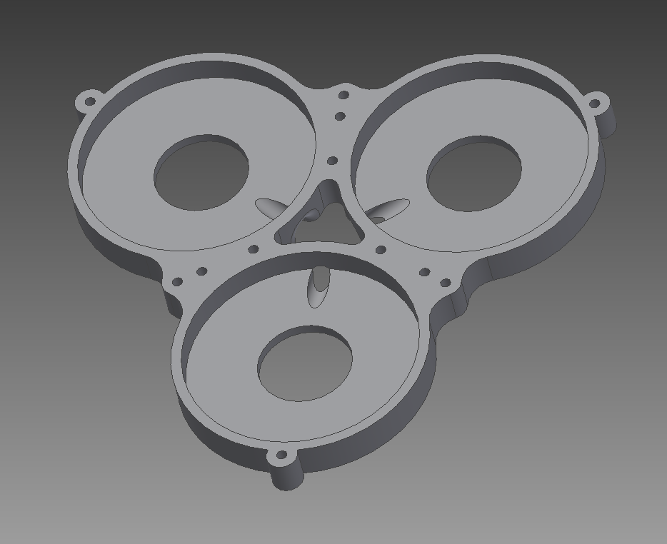
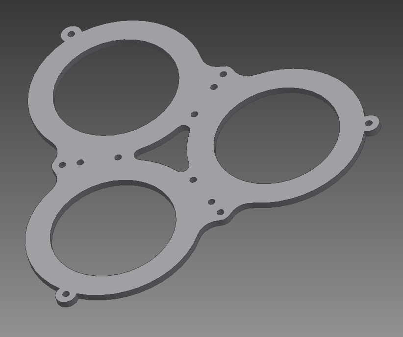
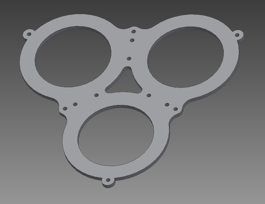
The top platform receives the second set of pneumatic actuators and completes the second section. The design is the same as for the middle platforms.
Bibliography
Robinson et al. (1999) Continuum robots-a state of the art
Walker et al. (2013) Continuous backbone “continuum” robot manipulators
McMahan et al. (2005) Design and implementation of a multi-section continuum robot: Air-Octor
Neppalli et al. (2007) Design, construction, and analysis of a continuum robot
Bosman et al. (2015) Domain decomposition approach for FEM quasistatic modeling and control of Continuum Robots with rigid vertebras
Duriez, et al. (2008) Contact skinning
Duriez et al. (2013) Control of elastic soft robots based on real-time finite element method
Contributors
Thor Bieze
Frédérick Largillière
Sandra Hage Chehade
Mario Sanz Lopez
Christian Duriez