Fabrication
The fabrication of the soft bending actuator with magnetic curvature sensor
The steps of fabrication can be summarized as follows:
Step 1: Two inner bodies (i.e., linear muscles) of the module are fabricated first using a three-dimensional (3D) printed mold and silicone rubber (Smooth-On Ecoflex 0030) (Figure.5).

Step 2: Inextensible sewing thread is wrapped and bonded around each linear muscle (Figure.6).

Step 3: With the flexible curvature sensor in the middle, two pieces of self-adhesive laminate sheet are laser cut and attached together to form the constraint layer (Figure.7).


Step 4: The constraint layer and two inner bodies are placed in a second 3D printed mold and filled with silicone rubber (Figure.9).

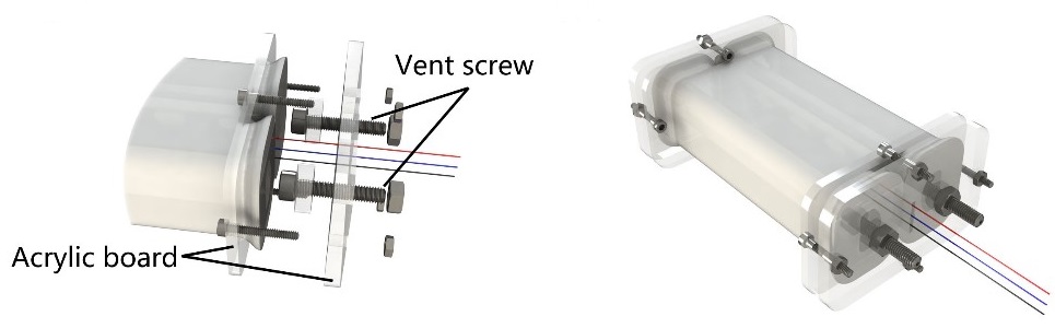
Step 5: Acrylic end-connector caps and vent screws are attached to both ends of the body (Figure.10).
The fabrication of the magnetic curvature sensor:
The entire fabrication process consists of three steps as below.
Step 1 : Circuit traces are designed and printed on a copper-clad flexible substrate (Pyralux, 3M, Figure.11(a)) using a solid ink printer (Xerox Color 8570, Figure.11(b)).

Step 2: The patterned copper-clad substrate is placed in a ferric chloride (Figure.12(a)) etching tank (Figure.12(b)) that remove all exposed copper, leaving the electrical traces intact. Usually take around 15 min.

Step 3: Discrete circuit components (AH49E) are soldered and the miniature magnet is mounted on its precise position using a microscope.